Engineering
Tracked undercarriage
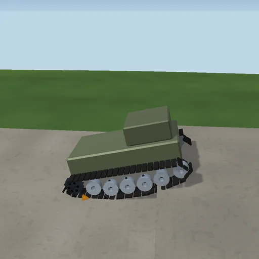
Drive an eight-tonne tracked carrier at a 0.5 m step: the sprocket’s belt grips the ground up to the friction limit, the idler meets the step face and rides up its corner, the taut belt span between the idler and the front wheel pushes against the corner with a force set by the track tension, and the five road wheels on their springs take the shock. Slacken the tension and the span yields; run the machine in the air and the belt spins up to the motor’s no-load speed with no thrust. Switch to a pivot turn and the two tracks, driven opposite ways, turn the hull against the lateral skid of the pads, settling at the yaw rate of the closed-form balance. Motor work is booked against kinetic and potential energy, slip, dampers and the step corner.
What happens
An 8 t tracked carrier in side view: a rigid hull with five road wheels, each its own body on a strut spring and a stiff guide, an idler and a sprocket; the ground is a polyline with a step, met by circle contacts with a normal spring-damper and a belt friction that saturates with the slip speed, and the belt span from the idler to the front wheel is a string under constant tension whose extra path over the step corner is a potential, so its lift and pull on the hull are its gradient. A shunt motor drives the sprocket against the belt’s thrust. In plan view the two tracks run opposite ways and the lateral skid of the pads along the contact length resists the yaw. Symplectic Euler at 20 µs; the motor work meets kinetic and potential energy and every heat to a part in ten thousand.
Try this
Watch the idler meet the step and the taut span lift the nose over the corner; slacken the tension and compare; switch to the pivot turn and read the yaw rate against the closed form.
The model and its limits
A planar hull with ideal road wheels, a massless belt whose only tension effect is the front span, a smoothed friction law, no track sag or soil mechanics; the turn is a lumped plan-view model. Not a mobility rating.
Equations used in the module
Equations
F_t = μ·F_n·clamp((v_belt − v_t)/v_s),  J_s·dω/dt = T_s·(1 − ω/ω_0) − F_t·r − c·ω
U_belt = T·(|c − a| + |i − c| − |i − a|),  F = −∇U_belt
I_z·dΩ/dt = (F_R − F_L)·B/2 − μ_l·W·L/4·clamp(Ω·L/4v_s)
W_motor = E_k + E_p + Q_slip + Q_ground + Q_damper + Q_drag + Q_corner