Engineering
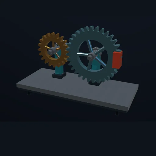
Spur gear pair
Increase the output load until the drive stalls. Change the tooth ratio and reverse the motor.
In development
Working mechanisms, manufacturing processes and machines: from an astrolabe and cable robot to a hydrofoil and a CNC mill.
106 modules · Page 1 / 6 · 54 planned
This Suite is still in development. These are implemented experiments, not a released product.
Contact & licencesEngineering
Increase the output load until the drive stalls. Change the tooth ratio and reverse the motor.
Engineering
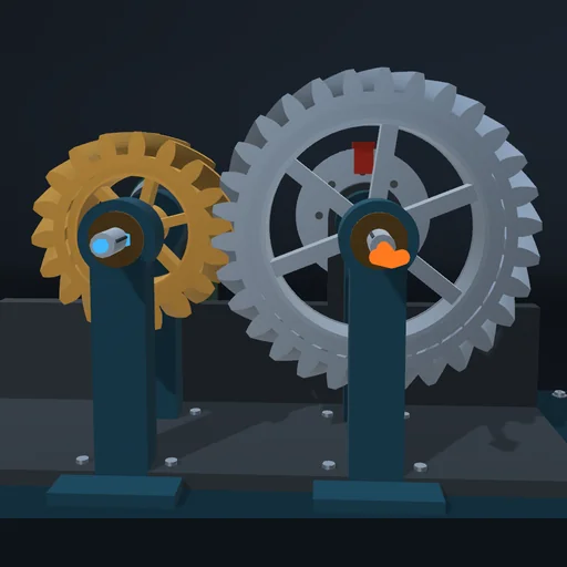
Change the helix angle and hand at the same load and read the axial thrust on the bearings. The tooth force is solved along the tooth normal; the thrust is a bearing reaction, not a formula.
Engineering
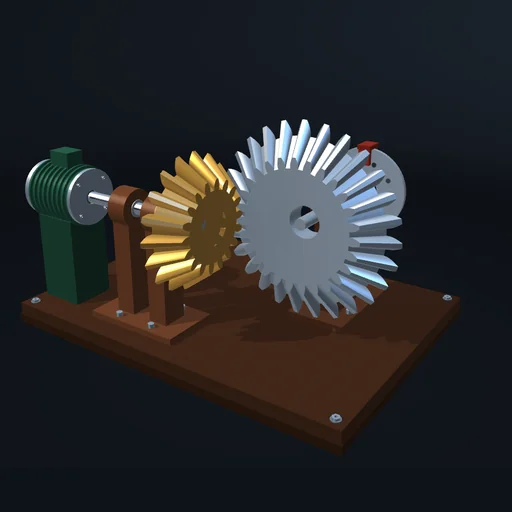
Turn the shafts to another angle and change the tooth ratio under the same load. The pitch cones follow; input and output power stay equal in the ideal mesh while torque and speed trade places.
Engineering
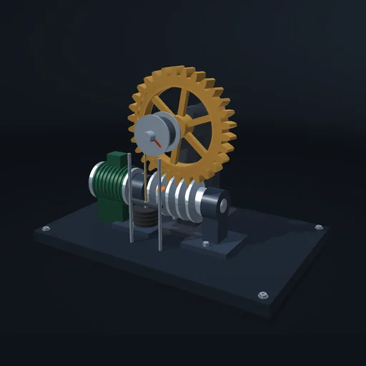
Lift a load through a worm and wheel, then stop the motor and lower the friction until the load turns the worm back. Compare one, two and four starts: the efficiency both ways and the brake needed to hold the load.
Engineering
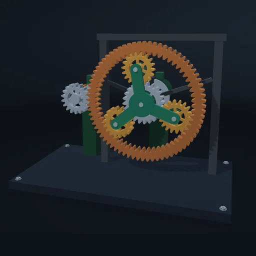
Hold the ring, then the sun, then the carrier, and drive the train: one equation ties the three speeds together. Drive the sun and the ring at once, then hold two members and try to turn the third.
Engineering
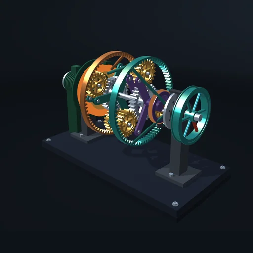
Shift a two-set planetary gearbox through first, second, third and reverse under a light and a heavy load; each gear is just a pair of clutches and brakes. Then apply both brakes at once and watch the box lock up.
Engineering
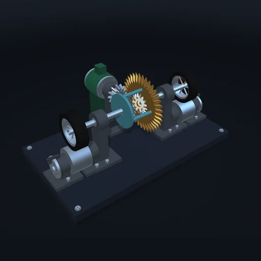
Put one wheel of an axle on a slippery drum: an open differential gives both wheels the same small torque, so one spins and the other stands. Add a limited-slip clutch or lock the differential with the same engine torque, and compare.
Engineering
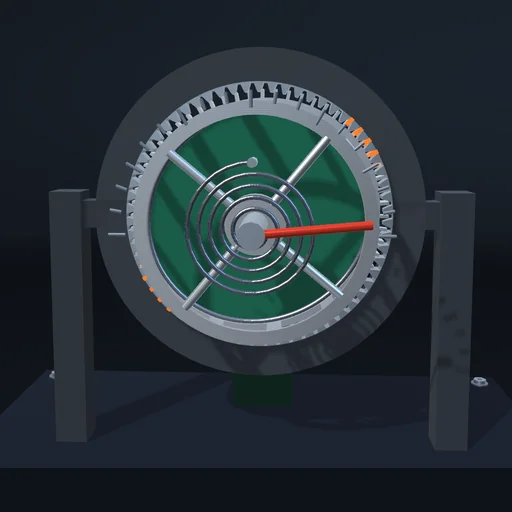
Wind a spring through a strain-wave gear and watch the elastic cup wind up by T/K; reverse and the spring gives its energy back. Compare two and three lobes, 60 and 120 teeth: the reduction is the flexspline’s teeth over the tooth difference.
Engineering
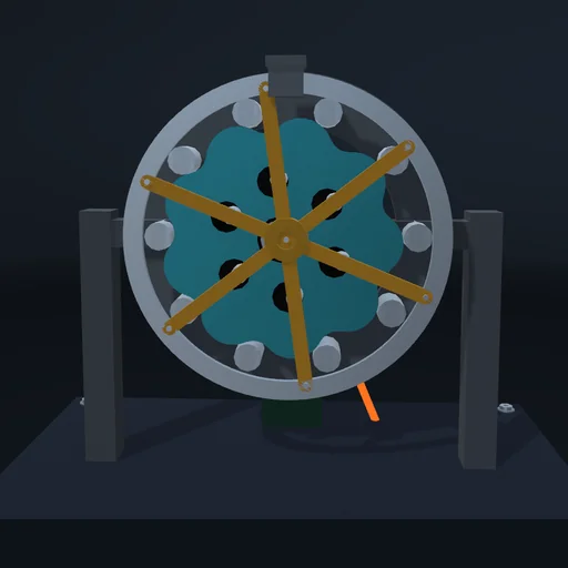
Run a cycloidal reducer with one disc and then with two half a turn apart, and compare the force on the input bearing. Reverse under load with more play in the output pins: the input turns on while the output stands.
Engineering
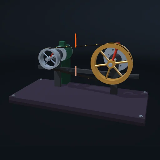
Raise the load until the belt slips, then add the tensioner and compare. The limit comes from the wrap angle and friction; while the belt slips, the work goes into heat.
Engineering
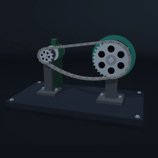
Drive a sprocket of 30 teeth through a roller chain from one of 9, 13 or 19 teeth and watch the driven speed ripple once per tooth. Then give the chain some slack and start again: the motor runs ahead until the run snaps tight.
Engineering
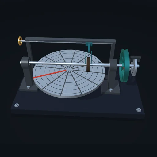
Shift the roller across the turning disc under a steady load: the output speed follows r/R through zero into reverse. Lower the press until the roller slides; then release the press and apply it again on the running disc, and compare the heat of the slip with the energy the flywheel takes up.
Engineering
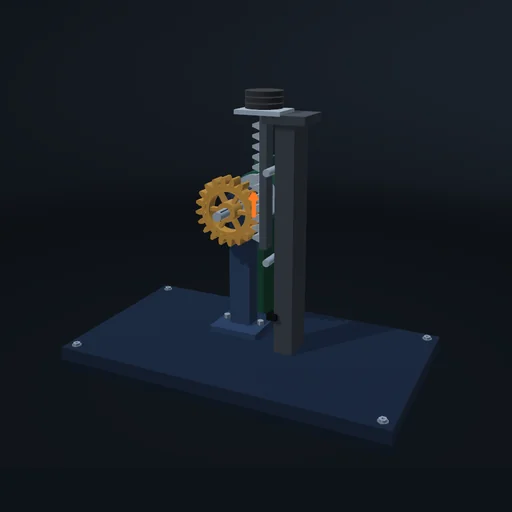
Lift a load with a vertical rack, then reverse the drive; turn the rack horizontal and reverse again. A hanging weight keeps one flank closed, a carriage on a rubbing guide has to cross the play first.
Engineering
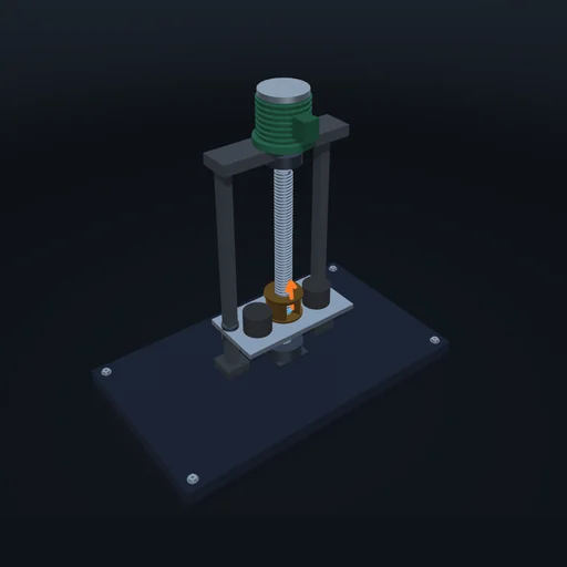
Lift the same load with screws of one, two and four starts and compare torque and efficiency; then switch the motor off and lower the friction until the load turns the screw back.
Engineering
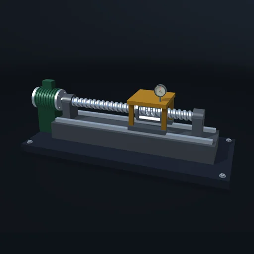
Move the carriage between two stations with a preloaded nut and with a nut that has play, and watch how far it lags the motor. Push the standing carriage to measure the nut’s stiffness, then switch the servo off and push again: the screw turns back.
Engineering
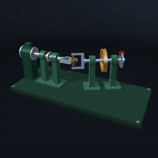
Bend the shaft and watch the output run unevenly at a steady input; add a second joint in phase to cancel it, or crossed to double it. Yokes and crosses are bodies on revolute joints.
Engineering
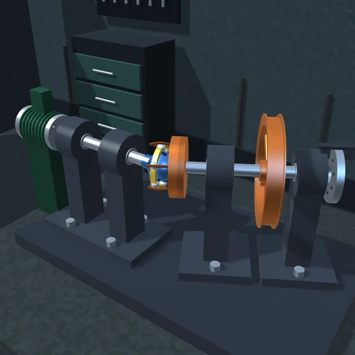
Bend the drive line and watch the output speed: through the Rzeppa joint it stays exactly that of the input, through a Cardan cross it swings between cos β and 1/cos β of it twice a turn. Watch the balls: the cage keeps them in the plane that halves the bend.
Engineering
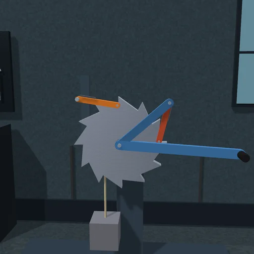
Swing the lever and the load climbs a tooth at a time: the driving pawl pushes a tooth forward, the holding pawl clicks over the teeth and catches the wheel when the lever goes back. Stop the lever: the load stays. Lift the pawls and let it run down, then drop them and watch the blow.
Engineering
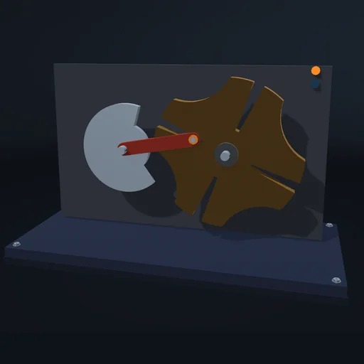
Compare four and six slots and raise the drive speed: one driver turn makes one index step, the dwell is held by the locking arc, and the wheel's peak acceleration grows with the square of the speed.
Engineering
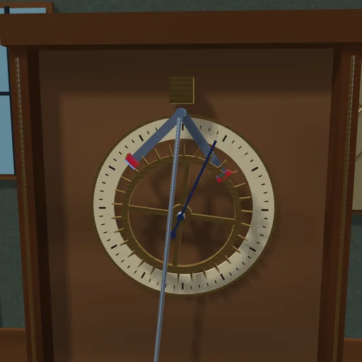
A seconds pendulum and the escape wheel of a clock meet only where the teeth touch the anchor’s pallets: a tooth rests on a locking face, the swing slides it off, it pushes the impulse face and drops onto the other pallet. Change the drive and watch the swing settle anew; hold the pendulum and see whether the clock starts again.
Some modules belong to more than one Suite. Shared experiments have one description here.