Engineering
Geneva indexing mechanism
Compare four and six slots and raise the drive speed: one driver turn makes one index step, the dwell is held by the locking arc, and the wheel's peak acceleration grows with the square of the speed.
What happens
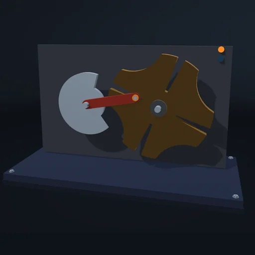
A driver with one pin turns steadily. Each time the pin enters a slot it turns the wheel by one slot pitch, 360°/n, and between steps the locking arc holds the wheel still. The pin enters and leaves the slots radially, so the wheel starts and stops without a jump in speed, but its acceleration jumps at the entry and peaks during the step. Compare 4, 5, 6 and 8 slots: with more slots each step is smaller and takes a larger share of the driver's turn, so the motion is gentler and the dwell shorter. Double the drive speed and the peak acceleration grows four times, and with it the inertial part of the pin force; a heavier wheel or a load torque raises the pin force, and the lock carries the load torque during the dwell.
Model: rigid driver and wheel; the pin is a point-in-slot joint on the slot it engages, the lock holds the wheel while the pin is outside; the driver motor holds its speed up to its torque limit, the load torque is constant. No friction, clearance or impact at the entry.
Try this
Compare the slot counts and raise the drive speed; watch the wheel acceleration and the pin force.
Equations used in the module
Equations
λ = r/C = sin(π/n)
tan ψ = λ sin φ / (1 − λ cos φ),  |φ| ≤ π/2 − π/n
Δψ = 2π/n,  Δφ = π − 2π/n
ε = d²ψ/dt² ∝ ω²