Engineering
Worm gear and backdriving
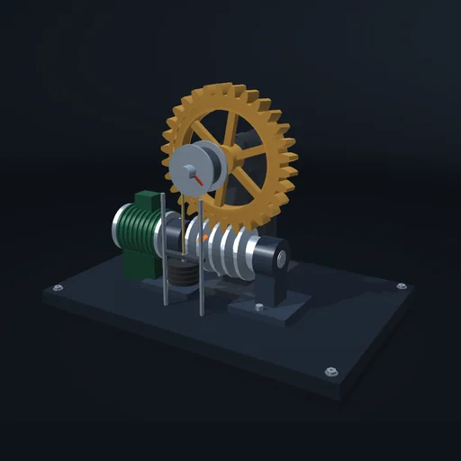
Lift a load through a worm and wheel, then stop the motor and lower the friction until the load turns the worm back. Compare one, two and four starts: the efficiency both ways and the brake needed to hold the load.
What happens
A motor turns a worm of pitch radius 0.2 m under a wheel of 30 teeth; a drum on the wheel’s shaft winds the rope of the load. The worm’s thread slides across the wheel’s teeth on a flank inclined at the lead angle λ, tan λ = z₁m/(2r₁): 5.7° for one start, 11.3° for two, 21.8° for four. Friction on the flank adds the friction angle φ = atan μ. Driving, the worm needs the torque F·r₁·tan(λ + φ), where F is the load’s force at the wheel’s pitch circle, and only tan λ/tan(λ + φ) of its work reaches the load: 45 % with one start and μ = 0.12, 73 % with four. Switch the motor off: while λ < φ the gear locks itself and the load stays. With two starts at μ = 0.12 the load turns the worm back and runs down; a brake on the worm holds it only from F·r₁·tan(λ − φ) up. Lower μ and even the single start lets go below μ = tan λ = 0.1.
Model: rigid worm, wheel, drum and load; the mesh is one flank contact at the pitch point with Coulomb friction that sticks or slides, the rope a rigid tie to the drum. No bearing friction, tooth elasticity, lubrication or wear; μ does not depend on speed.
Try this
Lift with one start and switch the motor off: the load stays. Choose two starts and repeat: the load runs back until the brake holds it.
Equations used in the module
Equations
tan λ = z₁m/(2r₁),  φ = atan μ
T₁ = F r₁ tan(λ + φ),  η = tan λ / tan(λ + φ)
T₁′ = F r₁ tan(λ − φ),  η′ = tan(λ − φ) / tan λ
λ ≤ φ  ⇒  T₁′ ≤ 0