Engineering
Differential under load
Put one wheel of an axle on a slippery drum: an open differential gives both wheels the same small torque, so one spins and the other stands. Add a limited-slip clutch or lock the differential with the same engine torque, and compare.
What happens
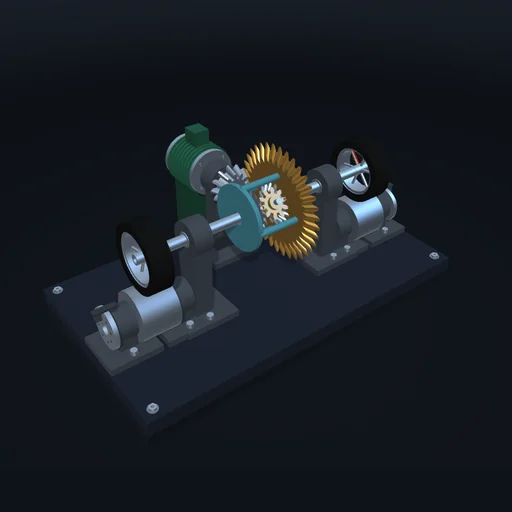
An engine drives a bevel pinion, and the pinion the ring gear on the differential case (3 : 1). Inside the case two spider gears on a cross pin mesh with two side gears, each on a half-shaft with a wheel; each wheel stands on a drum with its own brake. The gears leave one relation free, ωL + ωR = 2ω₀: the wheels may turn at different speeds, as in a curve. The spiders balance the torques, so an open differential always gives both sides the same torque. Lower the left tyre’s grip to 0.1: it slips at μN·r = 18 N·m, so the right wheel gets only 18 N·m too – less than its drum needs – and stands while the left one spins at twice the case speed. A limited-slip clutch between the left shaft and the case passes up to its preload: the right side gets the slipping side’s torque plus the preload. A locked differential turns both wheels together and gives each one whatever it needs.
Model: rigid gears on their own bearings, frictionless meshes in the turning case; the tyres and the clutch are friction couplings that stick or slip (Coulomb). No tyre deformation, rolling resistance or vehicle mass; the drums stand in for the road.
Try this
Lower the left grip to 0.1: the right wheel stops. Then choose limited slip or locked and compare.
Equations used in the module
Equations
ωL + ωR = 2ω₀
TL + TR = T₀
|TR − TL| ≤ Tc,  Tc = 0  ⇒  TL = TR
TL, TR ≤ μNr