Engineering
Bevel gears
Turn the shafts to another angle and change the tooth ratio under the same load. The pitch cones follow; input and output power stay equal in the ideal mesh while torque and speed trade places.
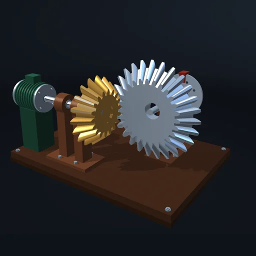
What happens
Two bevel gears on intersecting shafts. Their pitch cones share one apex, and the cone angles follow from the shaft angle Σ and the tooth numbers: the cones roll on each other without slipping along their common line. Change Σ between 60° and 120° and pick a ratio. The speed ratio stays z₁/z₂ whatever the angle: the speed falls and the torque rises in the ratio z₂/z₁, and with an ideal mesh the input power equals the output power. The tooth force acts across the plane of the two shafts, at the middle of the face width; the input bearing takes it, and its direction flips when the drive is reversed.
Model: rigid gears and shafts in fixed bearings; one ideal tooth contact at the mean point of the contact line along the common tangent; the speed ratio and the bearing loads come from the solver. No friction, backlash or tooth deflection; the motor holds its speed up to its torque limit, the load is a brake.
Try this
Change the shaft angle and the ratio under the same load and compare the input and output power.
Equations used in the module
Equations
tan δ₁ = sin Σ / (z₂/z₁ + cos Σ),  δ₂ = Σ − δ₁
|ω₂/ω₁| = z₁/z₂
P₁ = T₁ω₁ = T₂ω₂ = P₂