Engineering
Wall-climbing robot
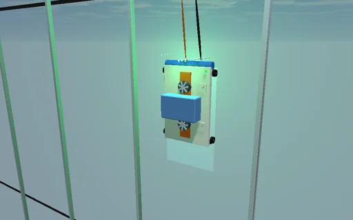
Send a window-cleaning robot up the glass facade of an office tower at bright noon, high above the city: two impellers evacuate its chambers until each fan curve meets the leakage under the skirt at a closed-form 2.7 kPa, and the suction presses its wheels to the glass. It holds while mu ΔP A outweighs its weight, and it does not peel while the moment of the suction about the lower wheels beats the overturning moment of its weight. Watch the pressure dip each time a lip slides over a silicone joint: with sound joints it climbs on, with open ones the wheels slip and it stops at the closed-form stall point. Load the water tank until the motors crawl, switch off a chamber or send a gust, and the rope grab on the safety line catches it; the work of the motors is followed into height, lip drag, slip and the rope.
What happens
A 9 kg robot with a 3 kg water tank climbs a glass facade. Two round chambers of 0.15 m radius (A = 0.0707 m², 4.2 L each) sit 0.15 m and 0.55 m above the lower axle of a 0.7 m wheelbase. Each impeller follows Q = Q0 sqrt(1 − ΔP/P0) with P0 = 4 kPa and Q0 = 20 L/s at full speed (P0 ∝ s², Q0 ∝ s); the air leaks in under the skirt as C_d L g sqrt(2ΔP/ρ) through a 0.3 mm gap on clean glass, so the chamber settles at ΔP = Q0²/(K² + Q0²/P0) = 2.70 kPa, relaxing as dΔP/dt = γ p_a/V (Q_fan − Q_leak), integrated with RK4. Where the lip rests on a 50 mm silicone joint the gap widens by the joint gap over (asin b − asin a)/π of the perimeter, up to 27 %: at 1.5 mm the pressure dips to 1.10 kPa. The wheels on wet glass (μ = 0.5) carry μ(ΣΔP A − W); the robot holds while that exceeds M g and does not peel while the top wheels stay loaded, ΣΔP A l_i > g Σ m h + W L/2 about the lower axle. Four geared motors give 240 N at stall falling to zero at 0.4 m/s; a speed controller drives them up to that line and the traction, the wet lip drags 0.006 s × ΣΔP L v. A gust pulls outward with a sin² profile over 4 s. A rope grab locks when the robot slides faster than 0.3 m/s; peeling hangs it on the safety line. Steps of 0.5 ms; the motors’ work is followed into height, lip drag, slip heat, the rope’s arrest and kinetic energy. The city below is a 1:20 model 18 m down.
Try this
Climb to 8 m and watch each chamber’s pressure dip at the joints; open the joints to 4 mm and see it stall at the closed-form point; load the tank until the motors crawl; switch off a chamber or blow a gust above the critical pull and the rope grab catches it.
The model and its limits
Quasi-uniform gaps under rigid skirts, an orifice law for the leakage, Coulomb wheels with one friction coefficient, a quasi-static moment balance without inertia, a rope that arrests instantly. Not a certified safety calculation of real rope-access or facade equipment.
Equations used in the module
Equations
Q_fan = s·Q0·√(1 − ΔP/(s²·P0)),  Q_leak = C_d·L·g·√(2ΔP/ρ),  g = g0 + g_j·(asin b − asin a)/π
dΔP/dt = γ·p_a/V·(Q_fan − Q_leak),  ΔP* = Q0²/(K² + Q0²/P0),  K = C_d·L·g·√(2/ρ)
hold: μ·(ΣΔP·A − W) ≥ M·g,  no peel: Σ ΔP·A·l_i > g·Σ m·h + W·L/2
M·a = min(F_m(v), μN) − M·g − c·ΣΔP·L·v,  W_motor = ΔE_p + W_lip + W_slip + E_rope + E_k