Engineering
Quick-return mechanism
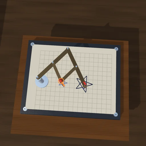
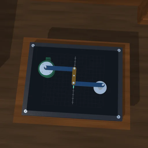
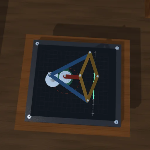
The crank turns steadily, yet the ram cuts slowly and comes back fast. Change the crank radius and watch the time ratio of the strokes; load the cut and see the motor torque rise on the slow stroke while the wheel carries the ram through the quick return.
What happens
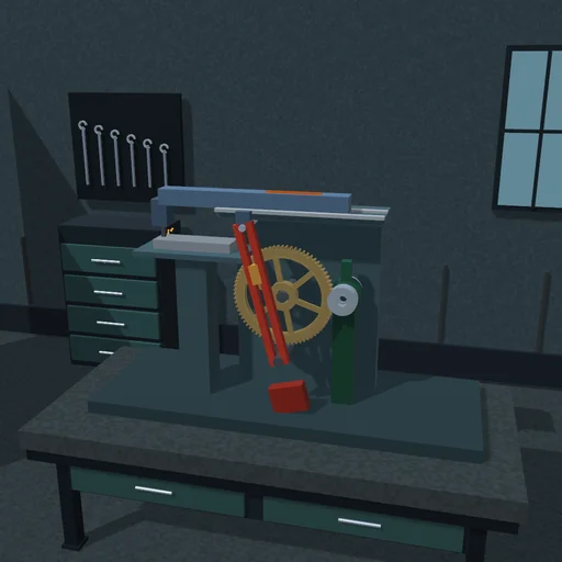
The drive of a shaping machine. A motor turns the bull wheel; its crank pin, r from the centre, slides in the slot of a lever that swings about a pivot d = 0.45 m below the wheel’s centre. The lever, 1 m long, moves the ram through a pin in the ram’s slot. The lever turns back where it touches the circle of the crank pin, sin α = r/d: over the wheel’s far side, π + 2α of each turn, the pin is far from the pivot and the ram runs slowly, cutting; over the near side, π − 2α, it returns fast. With r = 0.25 m the strokes last 2.2 to 1 and the ram travels 2·L·r/d = 1.11 m; with r = 0.30 m, 2.7 to 1 and 1.33 m.
While the tool is over the workpiece on the cutting stroke the ram meets the cutting force: the motor torque rises on the slow stroke - with the pin at the top, F·L·r/(d + r), 71 N·m for 200 N - and each stroke does 180 J of cutting work for 300 N over the 0.6 m workpiece. The heavy wheel carries the ram through the return.
Model: rigid wheel, lever and ram; the pins slide in the slots without friction; a motor with a torque cap holds the crank’s speed. Weights left out.
Try this
Watch the timer: the slow stroke and the return. Shorten the crank and compare the ratio; raise the cutting force and watch the motor torque.
Equations used in the module
Equations
sin α = r/d
t_cut = (π + 2α)/ω,  t_return = (π − 2α)/ω
stroke = 2·L·r/d
v_max = L·r·ω/(d ± r)
τ = F·L·r/(d + r)  (pin at the top)