Engineering
Watt straight-line linkage
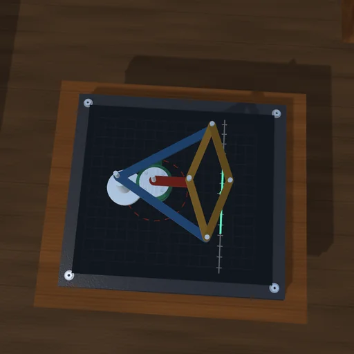
Swing the left lever and watch the pen in the middle of the coupler: within ±15° it stays within a fraction of a millimetre of the ruled line, then curls away. Move a support or change the bars and compare the path; push across the line and see the motor feel the push only away from the centre.
What happens
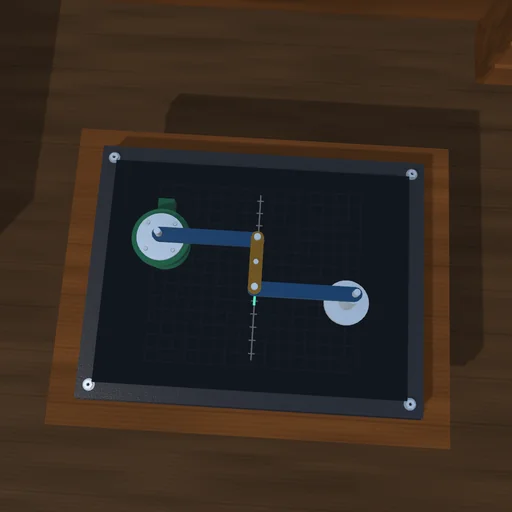
Two levers of 0.7 m turn on fixed supports and point at each other; a coupler of 0.35 m joins their tips. The pen in the coupler’s middle M runs very nearly straight, across the levers: with the left lever at 10° it has gone 122 mm along the line and strays 0.06 mm off it, at 20° 245 mm and 2.1 mm, and further out the path curls away. The loop locks where the coupler lines up with the right lever, at +29.3° and −57.4° here; the servo stops 2° short. Nothing guides M along the line - its path is what the four pins leave it.
Push across the line at M. With the levers level they carry the push straight into the supports, half each, and the motor feels nothing; at 15° it must hold F·∂M_u/∂θ₁, 0.91 N·m for 100 N. Move the right support by 2 cm and the line leans and bows, 2.4 mm within ±20°.
Model: rigid levers and coupler on four revolute joints, solved together every step; a servo with a torque cap drives the left lever’s pin. No friction or elasticity.
Try this
Swing the lever ±20° and read the deviation. Then set the lever still near 15° and push across the line: the motor torque appears.
Equations used in the module
Equations
A = P₁ + a·e(θ₁),  B = P₂ − a·e(θ₂),  |A − B| = c
M = (A + B)/2
τ = −F·∂M_u/∂θ₁
F₁ = F₂ = F/2  (θ₁ = 0)