Engineering
Flywheel energy storage
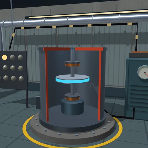
Cover a load’s power pulses that the grid connection alone cannot: the flywheel gives energy as it slows and takes it back as it speeds up. Compare the rotors, let the vessel fill with air and watch it coast down.
What happens
A rotor on a vertical shaft spins in a vacuum vessel on magnetic bearings; a motor-generator under it is joined through a converter to a bus. The bus feeds a load of 30 kW with pulses of 200 kW, and the grid connection gives at most 50 kW. What the grid cannot give, the rotor gives: it slows, and its energy J·ω²/2 reaches the bus at 96 % efficiency; between the pulses the grid speeds it up again. The converter works between 300 and 1000 rad/s, its torque is held to 400 N·m and its power to 250 kW, so at low speed it can give only η·T·ω.
A steel disc of 20 kg·m² at 1000 rad/s holds 2.78 kWh, 91 % of it above 300 rad/s. A pulse of 20 s takes it down to 802 rad/s: the rotor gives the bus 3.60 MJ, and only 4.5 kJ of the load goes unserved while the machine’s torque catches up. The light disc of 10 kg·m² runs out during a pulse of 40 s: it reaches 300 rad/s and 2.84 MJ go unserved. In vacuum an hour of standby costs 1.02 MJ, from 1000 to 948 rad/s; in air the windage brings the rotor down to 348 rad/s. Charged and discharged at 100 kW, the steel disc returns 91.7 % of the energy.
Model: one rigid rotor, J·dω/dt = T − b·ω − c·ω², with bearing drag and windage; the machine’s torque follows the converter’s command with a lag of 20 ms, and the efficiency acts on the electrical side; RK4 at 1/120 s. No stresses in the rotor, no losses in the bearings beyond the drag.
Try this
Watch the next pulse: the grid gives its 50 kW and the flywheel the rest. Take the light disc and lengthen the pulse until lamps go red, then let air into the vessel and speed up the time.
Equations used in the module
Equations
E = J·ω²/2
J·dω/dt = T − b·ω − c·ω²
P_bus = η·T·ω (giving),  T·ω/η (taking)
|T| ≤ 400 N·m,  |P| ≤ 250 kW