Engineering
Hydraulic cylinder
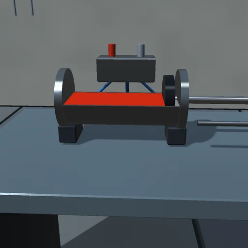
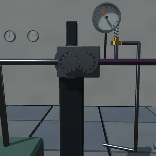
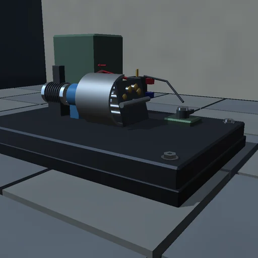
Lift a load with a double-acting cylinder through a spool valve and read both chamber pressures: at equal inflow to the working chamber, retraction is faster than extension because the rod takes part of the piston’s area; shut the valve and the load hangs on the oil column, creeping by the seals’ leak; soften the oil with entrained air and the pressure builds more slowly. The supply’s pQ is booked against the load’s Fv, the throttling, the leak and the oil’s compression.
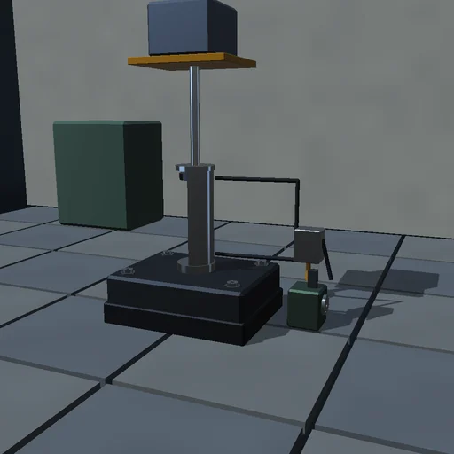
What happens
A vertical cylinder of 50 mm bore and 28 mm rod lifts 200 kg through a four-way spool valve from a 100 bar supply. The valve’s orifices pass turbulent flow C_d·A·√(2Δp/ρ); each chamber’s pressure follows dp/dt = β/V·(Q − A·v − K·p) with the oil’s bulk modulus and an external leak past the seals; the piston sees the pressures on its two areas, the load, smoothed Coulomb and viscous friction, and elastic end stops. The rod-side area is 69 % of the piston's, so equal chamber inflow gives faster retraction. Equal valve opening does not guarantee equal flow: speed also depends on the load and return-side back pressure. RK4 at 20 µs; the supply’s pQ is found again in the load’s work, the kinetic energy, the friction, the valve’s throttling, the leak and the compression of the oil.
Try this
Extend, then retract with the same spool and compare the speeds and the pressures; shut the valve and read the creep; soften the oil and watch the pressure rise more slowly.
The model and its limits
Lumped chambers at uniform pressure, orifice flow with a constant discharge coefficient, laminar leakage to the drain, no hose dynamics or pump ripple, pressures clamped at zero instead of cavitation modelling.
Equations used in the module
Equations
Q = C_d·A_v·√(2·Δp/ρ)
dp_A/dt = β/V_A·(Q_A − A_p·v − K·p_A)
m·dv/dt = p_A·A_p − p_B·A_r − F − F_fr
p_s·Q_s = F·v + Σ Q·Δp + K·(p_A² + p_B²) + Σ p·dV_c/dt