MakarovSuites
English
EnglishDeutschРусскийУкраїнськаFrançaisEspañolItalianoPolski
Contact & licences

Engineering

Axial piston pump

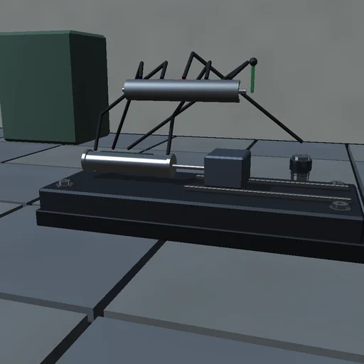
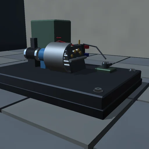
Tilt the swash plate of a nine-piston pump and watch line A fill to the pressure the load orifice demands: the displacement follows tan of the swash angle, reversing it sends the flow round the other way, zero swash leaves the motor idling at its no-load speed. Count the flow ripple of nine pistons and compare it with the closed form, block the load and let the relief valve take the whole flow, lower the charge pressure and see the return line starve. Shaft and charge work are booked against the pressure energy in the lines and the losses in the orifice, the leaks and the relief.
Axial piston pump — Actual application image
Actual application image

What happens

A motor turns the cylinder block of an axial piston pump against a tilted swash plate: each of nine pistons strokes with cos θ, the kidney ports of the valve plate hand a chamber to line A while its volume shrinks and to line B while it grows, so the displacement per turn is n·A·2R·tan α and the delivered flow ripples at the kinematic rate of nine pistons. The two lines are compressible oil volumes joined by a load orifice, external and cross-port leaks, a charge pump topping up whichever line falls below its pressure and relief valves opening over a 10 bar band; a shunt motor drives the shaft. RK4 at 20 µs; the shaft and charge work meet the stored pressure energy and every loss to rounding.

Try this

Tilt the swash and read line A climb; reverse it and B takes over; set it to zero and the motor runs free. Compare the ripple with the closed form, then block the load and watch the relief take the flow.

The model and its limits

Rigid pistons without slipper leakage or barrel tilt, a lumped line volume with constant bulk modulus, a linear relief band, a straight motor line. Pressures and ripple are those of this idealized pump.

Equations used in the module
Equations
V_g = n·A·2R·tan α,  dV_k/dφ = A·R·tan α·cos θ_k
dp_A/dt = (β/V_L)·(Σ Q_k − Q_load − Q_leak − Q_relief + Q_charge)
J·dω/dt = T_s·(1 − ω/ω_0) − Σ p_k·dV_k/dφ − T_f − c·ω
δ_odd = (π/2n)·tan(π/4n),  δ_even = (π/n)·tan(π/2n)
Related experiments

Back to catalogue
Centrifugal pump — Actual application image

Engineering

Centrifugal pump

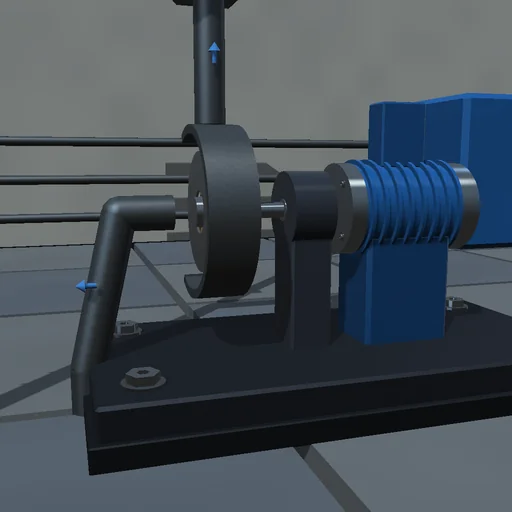
Run a centrifugal pump into a pipe that lifts water ten metres: the flow settles where the pump curve H = K1 w^2 - K2 w Q - K3 Q|Q| crosses the system curve Hs + R Q|Q|, exactly the closed-form root. Throttle the discharge valve and watch the point climb the pump curve at less flow and more head; slow the motor and compare with the affinity laws, which hold only when the static head is taken away; drop below the speed whose shutoff head equals the lift and the flow stops. The motor’s work is booked against the lift, the pipe and internal losses, the disk friction and the kinetic energy of wheel and water.

Hydraulic motor — Actual application image

Engineering

Hydraulic motor

Feed a fixed-displacement motor from a 150 bar line through an inlet orifice and let it drain through another: free, it settles where the two throttles and friction use up the supply pressure, the closed-form speed of that balance. Load the brake and read the pressure difference climb as D dp / 2 pi meets brake plus friction; load it past the supply’s torque and it stalls. Drive the shaft from outside and the machine turns into a pump, lifting the outlet above the inlet; drive it faster than the inlet can feed and the inlet line drains to vapour pressure, the shortfall booked as cavitation. Supply and external work are booked against the throttling, the leaks, the heat and the stored energy.

Valve-controlled actuator — Actual application image

Engineering

Valve-controlled actuator

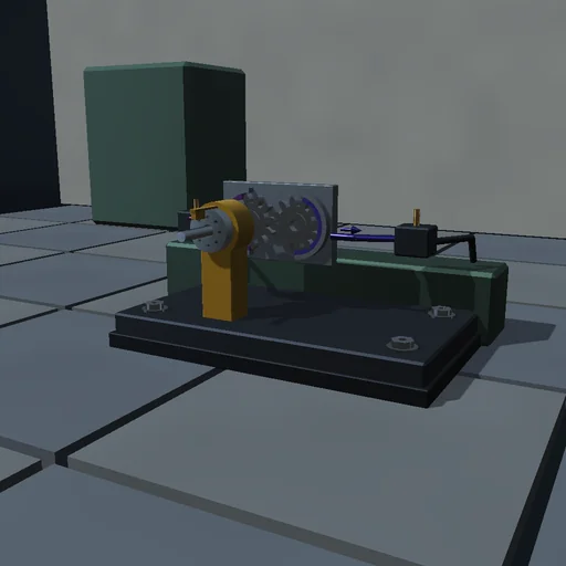
Move the command of a four-way spool and watch the slide follow: with a closed-centre spool nothing happens inside the lap, then the speed lands on the quasi-static balance of the two metering orifices and friction, and at null the load is held tight. Switch to an open-centre spool and the valve leaks 2 Cd w u sqrt(ps/rho) at null while both chambers sit at half the supply, but the smallest command tilts the pressures steeply towards the load. Push against the slide and read the pressure difference it needs. The supply’s pQ is booked against the throttling, the load’s Fv, the friction and the oil’s compression.