MakarovSuites
English
EnglishDeutschРусскийУкраїнськаFrançaisEspañolItalianoPolski
Contact & licences

Engineering

Hydraulic motor

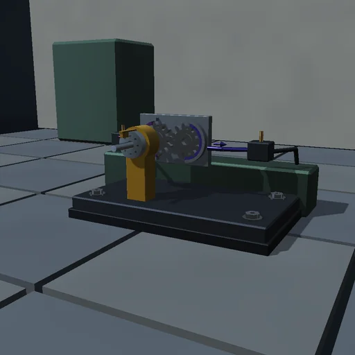
Feed a fixed-displacement motor from a 150 bar line through an inlet orifice and let it drain through another: free, it settles where the two throttles and friction use up the supply pressure, the closed-form speed of that balance. Load the brake and read the pressure difference climb as D dp / 2 pi meets brake plus friction; load it past the supply’s torque and it stalls. Drive the shaft from outside and the machine turns into a pump, lifting the outlet above the inlet; drive it faster than the inlet can feed and the inlet line drains to vapour pressure, the shortfall booked as cavitation. Supply and external work are booked against the throttling, the leaks, the heat and the stored energy.
Hydraulic motor — Actual application image
Actual application image

What happens

A gear motor of 50 cm³ per turn sits between an inlet line fed from a 150 bar supply through an orifice and an outlet line draining through another. The chambers pass D·ω/2π, the ideal torque is D·Δp/2π, cross-port and case leaks bleed the lines, Coulomb friction keeps a stick state, a brake and an external torque load the shaft. A symplectic sub-step of 20 µs takes the chamber flow at the mid-step speed and the torque at the mid-step pressures, so the hydraulic and mechanical ledgers meet exactly; when an overrunning load asks for more than the inlet orifice can feed, the inlet line drains to vapour pressure and the shortfall is booked as cavitation.

Try this

Let the motor run free and compare with the closed-form speed; load the brake until it stalls; then drive the shaft from outside and watch it become a pump, and harder until the inlet cavitates.

The model and its limits

Lumped lines with a constant bulk modulus, laminar leaks, turbulent orifices, vapour at zero absolute pressure without release dynamics, a rigid shaft. Efficiencies are those of this idealized machine.

Equations used in the module
Equations
Q_m = D·ω/2π,  T_i = D·(p_in − p_out)/2π
Q_in = C_d·A_in·√(2(p_s − p_in)/ρ),  Q_out = C_d·A_out·√(2p_out/ρ)
J·dω/dt = T_i + T_ext − T_f·sgn ω − T_b·sgn ω − c·ω
p_s·Q_in + T_ext·ω = ΔE_k + ΔE_p + Q_in_loss + Q_out_loss + Q_leak + Q_cav + Q_heat
Related experiments

Back to catalogue
Valve-controlled actuator — Actual application image

Engineering

Valve-controlled actuator

Move the command of a four-way spool and watch the slide follow: with a closed-centre spool nothing happens inside the lap, then the speed lands on the quasi-static balance of the two metering orifices and friction, and at null the load is held tight. Switch to an open-centre spool and the valve leaks 2 Cd w u sqrt(ps/rho) at null while both chambers sit at half the supply, but the smallest command tilts the pressures steeply towards the load. Push against the slide and read the pressure difference it needs. The supply’s pQ is booked against the throttling, the load’s Fv, the friction and the oil’s compression.

Air compressor — Actual application image

Engineering

Air compressor

Start a single-cylinder compressor on a ten-litre receiver and watch the gauge climb: each stroke draws air through the intake plate, squeezes it hot and pushes it past the delivery plate once the cylinder beats the tank. The mass delivered per cycle shrinks as the tank fills, close to the clearance-volume closed form 1 - c ((p/p0)^(1/n) - 1); a larger clearance delivers less. At the set pressure the switch stops the motor, the unloader vents the cylinder and the machine coasts to rest; open the consumer and the tank settles where delivery meets the bleed. Motor work and intake enthalpy are booked against the gas’s internal energy, the heat to wall and room and the air sent on.

Steam engine mechanism — Actual application image

Engineering

Steam engine mechanism

Open the throttle on a horizontal engine fed with 6 bar air and watch the slide valve lead the piston: the eccentric’s lap and advance are solved so the steam port cracks open by the lead at dead centre and shuts at the chosen cutoff, exactly acos(1 - 2c) of crank angle. Shorten the cutoff and the air expands in the cylinder, less air per joule of work but less work per cycle; load the brake until the mean effective pressure can no longer carry it and the engine stalls; park the crank at dead centre and it will not start. The admitted enthalpy is booked against the exhaust, the wall, the gas’s energy and the indicated work, and the indicated work against the flywheel, the friction and the brake.