Engineering
Steam engine mechanism
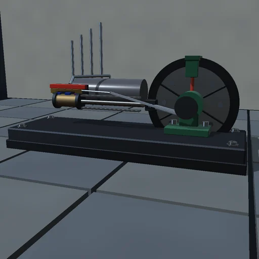
Open the throttle on a horizontal engine fed with 6 bar air and watch the slide valve lead the piston: the eccentric’s lap and advance are solved so the steam port cracks open by the lead at dead centre and shuts at the chosen cutoff, exactly acos(1 - 2c) of crank angle. Shorten the cutoff and the air expands in the cylinder, less air per joule of work but less work per cycle; load the brake until the mean effective pressure can no longer carry it and the engine stalls; park the crank at dead centre and it will not start. The admitted enthalpy is booked against the exhaust, the wall, the gas’s energy and the indicated work, and the indicated work against the flywheel, the friction and the brake.
What happens
A horizontal mill engine of 100 mm bore and 150 mm stroke runs on 6 bar air so the valve events show without condensation. A D-slide valve on an eccentric of 20 mm throw admits air to each end of the double-acting cylinder and exhausts the other; its lap and angular advance are solved by bisection so the port opens by the 1 mm lead at dead centre and closes at the chosen cutoff. Each chamber has compressible flow through its ports in both directions and exchanges heat with the wall; the flywheel of 3.2 kg·m² carries the crank through the dead centres against friction and a brake. RK4 at 20 µs; the admitted enthalpy meets the exhaust, the wall, the gas’s energy and the indicated work, and the indicated work meets the flywheel, friction and brake, both to rounding.
Try this
Read the cutoff angle against acos(1 − 2c); shorten the cutoff and compare the work per cycle and the air per joule; load the brake until the engine stalls; start it from dead centre and it will not move.
The model and its limits
Air as an ideal gas instead of steam, a lumped wall temperature, a D-valve without leakage or valve-rod geometry, no condensation or clearance effects beyond a fixed fraction. Indicator figures are those of this air engine.
Equations used in the module
Equations
x_v = e·cos(θ − δ),  cos δ = (l + L)/e,  θ_c = acos(1 − 2c)
A_s = w·max(0, x_v − l),  A_e = w·max(0, −x_v)
J·dω/dt = (p_h − p_c)·A·dx/dθ − T_f·sgn ω − T_b·sgn ω − c·ω
MEP = W_cycle/(2V_s),  H_in = ΔU + W_i + H_out + Q_wall