MakarovSuites
English
EnglishDeutschРусскийУкраїнськаFrançaisEspañolItalianoPolski
Contact & licences

Engineering

Pneumatic cylinder

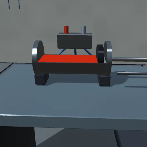
Drive a carriage with compressed air and watch the two chambers fill and empty through choked orifices: throttling the inlet leaves the piston on a soft cushion while throttling the exhaust holds it stiff between two high pressures. Shut both ports to make a gas spring whose frequency the trapped air sets, and compare a chamber that compresses adiabatically with one that stays at the wall’s temperature.
Pneumatic cylinder — Actual application image
Actual application image

What happens

A 40 mm cylinder with a 16 mm rod pushes a 5 kg carriage along a 300 mm stroke from a 6 bar supply. Each chamber keeps its own mass and temperature: air enters and leaves through orifices with the St. Venant–Wantzel flow function, choked below the critical pressure ratio 0.528, and the energy balance d(m·c_v·T) = c_p·T_in·G_in − c_p·T·G_out − p·dV + h·A·(T_w − T) makes a chamber adiabatic without heat transfer and isothermal with much of it. The throttle sits on the inlet (meter-in) or the exhaust (meter-out); with both ports shut the trapped air is a spring of stiffness γ·p·A²/V. RK4 at 10 µs, with the air drawn, exhausted and breathed in booked so the mass balance closes.

Try this

Extend with the throttle on the inlet, then on the exhaust, and compare the chamber pressures; shut both ports mid-stroke and watch the carriage bounce on the gas spring; set the heat transfer to zero and read the compression heating.

The model and its limits

Ideal gas with constant heat capacities, orifices with a constant discharge coefficient, uniform chamber temperature, a constant wall temperature; friction smoothed over 1 mm/s. Not a sizing tool.

Equations used in the module
Equations
G = C_d·A·p_u·√(γ/(R·T_u))·(2/(γ+1))^((γ+1)/(2(γ−1))),  r ≤ 0.528
G = C_d·A·p_u·√(2γ/((γ−1)·R·T_u))·√(r^(2/γ) − r^((γ+1)/γ))
d(m·c_v·T)/dt = c_p·T_in·G_in − c_p·T·G_out − p·dV/dt + h·A·(T_w − T)
ω² = γ·(p_A·A_p²/V_A + p_B·A_r²/V_B)/m
Related experiments

Back to catalogue
External gear pump — Actual application image

Engineering

External gear pump

Run a gear pump into a load valve and close the valve: the pressure, the slip leakage and the motor’s torque rise together until the relief valve lifts and the motor slows on its torque line. Open the gears’ clearance and watch the volumetric efficiency fall at the same drive; without leakage the mean flow is exactly the displacement times the speed. The shaft’s work is booked against the useful flow, the leak, the relief and the friction.

Axial piston pump — Actual application image

Engineering

Axial piston pump

Tilt the swash plate of a nine-piston pump and watch line A fill to the pressure the load orifice demands: the displacement follows tan of the swash angle, reversing it sends the flow round the other way, zero swash leaves the motor idling at its no-load speed. Count the flow ripple of nine pistons and compare it with the closed form, block the load and let the relief valve take the whole flow, lower the charge pressure and see the return line starve. Shaft and charge work are booked against the pressure energy in the lines and the losses in the orifice, the leaks and the relief.

Centrifugal pump — Actual application image

Engineering

Centrifugal pump

Run a centrifugal pump into a pipe that lifts water ten metres: the flow settles where the pump curve H = K1 w^2 - K2 w Q - K3 Q|Q| crosses the system curve Hs + R Q|Q|, exactly the closed-form root. Throttle the discharge valve and watch the point climb the pump curve at less flow and more head; slow the motor and compare with the affinity laws, which hold only when the static head is taken away; drop below the speed whose shutoff head equals the lift and the flow stops. The motor’s work is booked against the lift, the pipe and internal losses, the disk friction and the kinetic energy of wheel and water.