Engineering
Flywheel and balancing
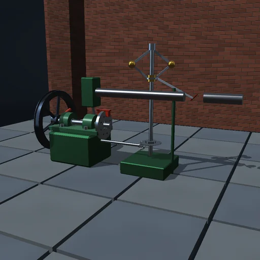
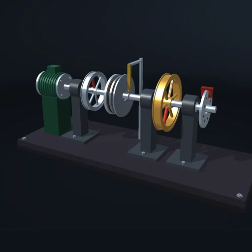
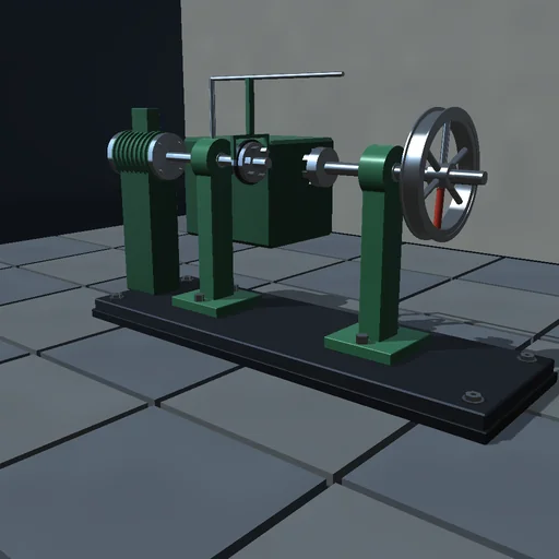
Smooth a pulsating drive with a heavier flywheel and read the speed fluctuation fall as 1/J; then add an unbalance bob to the rim, watch the stand whirl on its rubber mounts, run through the mounts’ resonance and place a counterweight that cancels the vibration. A torque impulse shows how much a flywheel resists a change of speed.
What happens
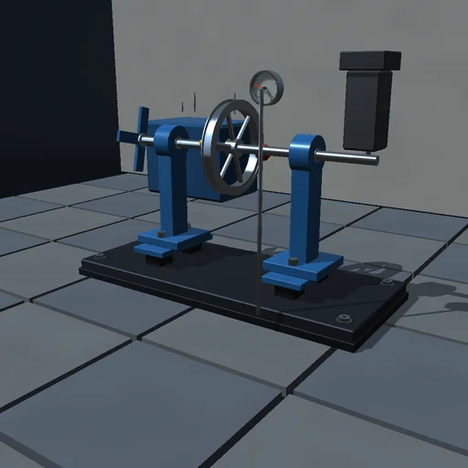
A shaft with a flywheel runs on two pedestals that stand on rubber mounts. A single-cylinder drive gives a torque T_0·(1 + A·sin nφ) against a fan load proportional to speed, so the speed pulses once or twice a turn and the flywheel’s inertia sets how much: δ ≈ 2T_0·A/(n·J·ω²). An unbalance bob on the rim and a counterweight at a set angle leave a residual unbalance whose centrifugal force whirls the whole rotor on the mounts as a Jeffcott rotor, largest at the mounts’ resonance √(k/M). RK4 at 0.1 ms on the angle, the speed and the two mount coordinates.
Try this
Raise the flywheel mass and read the fluctuation fall; then set an unbalance, run the speed through the mounts’ resonance, and cancel the whirl with a counterweight opposite the bob.
The model and its limits
Rigid shaft, isotropic mounts moving in the plane across the shaft, a prescribed torque law and a speed-proportional load, no gyroscopic or bearing effects. A teaching stand, not a balancing machine.
Equations used in the module
Equations
J·dω/dt = T_0·(1 + A·sin nφ) − T_0·ω/ω_s
δ = (ω_max − ω_min)/ω ≈ 2·T_0·A/(n·J·ω²)
M·d²x/dt² + c·dx/dt + k·x = U·ω²·cos φ
X = U·ω²/√((k − M·ω²)² + (c·ω)²)