Math
Gimbal lock and quaternions
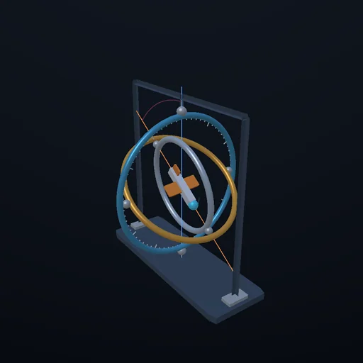
Three nested rings hold a platform: yaw, pitch, roll. Tip the middle ring to 90 degrees and the outer and inner rings line up - two rings, one axis, a degree of freedom gone. The readings flip by half a turn while the platform barely moves; the quaternion for the same motion never notices. Apollo flew with three rings and a red zone on the ball.
What happens
Three rings, one inside the other, hold a platform so it can face any way at all: the outer ring turns about the vertical (yaw), the middle ring about the outer ring's crossbar (pitch), the inner ring about the middle ring's (roll). Three angles, three rings - and that is exactly how the inertial platform in the Apollo command module was built. Now tip the middle ring up to 90 degrees. The inner ring's axis has swung until it lies along the outer ring's axis: two rings turning about one line. Whatever they do, there is a direction the platform can no longer turn in without both rings racing round together, and at exactly 90 there is none at all - the third degree of freedom is gone. That is gimbal lock. The numbers say it plainly: the matrix that turns ring rates into the platform's motion has determinant cos θ, one when level, zero at the pole. Ask the rings to produce a slow, steady turn about a horizontal axis and the roll ring must run at 1/cos θ and the yaw ring at tan θ - 2 and 1.7 times faster at 60 degrees, 57 times at 89, no finite rate at 90. Watch the tumble: the platform turns at one radian a second about an axis tilted slightly from horizontal, so it passes NEAR the pole once a turn. Its nose draws a perfectly smooth curve, but at the top the outer ring whips through nearly half a turn at cot α - almost six times the platform's own speed at 10 degrees of tilt. Set the tilt to zero and the readings simply jump: yaw and roll both read 180 a hundredth of a degree after they read 0. The platform did nothing of the kind. The quaternion - four numbers on a unit sphere - describes the same motion and moves at exactly one half every instant, at the top as at the bottom; it has no pole, which is why every flight computer since has kept its attitude that way and only derived the angles for the crew. Collins, coming home on Apollo 11, asked for a fourth gimbal for Christmas.
Equations used in the module
Equations
orientation:  R = Rz(ψ)·Ry(θ)·Rx(φ) - outer, middle, inner ring
bearing axes (world):  z,  Rz(ψ)·y,  Rz(ψ)·Ry(θ)·x;  at θ = 90° the third is (0, 0, −1) - the first axis's line
Jacobian:  ω = J·(ψ', θ', φ') with the three axes as columns;  |det J| = cos θ;  rank 2 at θ = ±90°
rates for ω = x at yaw 0:  ψ' = tan θ,  θ' = 0,  φ' = 1/cos θ;  at 60°: 1.73 and 2;  at 89°: 57.29 and 57.30;  at 90°: none
readings:  θ = asin(−R₃₁),  ψ = atan2(R₂₁, R₁₁),  φ = atan2(R₃₂, R₃₃);  the flip: Ry(89.99°) reads (0, 89.99, 0), Ry(90.01°) reads (180, 89.99, 180)
tilted turn:  axis (sin α, cos α, 0), 1 rad/s;  peak pitch 90° − α;  yaw = atan2((1 − cos t) sin α cos α, (1 − cos t) sin²α + cos t);  peak yaw rate cot α:  30° → 1.732,  10° → 5.671,  2° → 28.64
quaternion:  q = (cos a/2, n sin a/2),  q' = q_step·q,  |q| = 1;  |dq/dt| = ½|ω| every instant, 0.4999986 at dt = 1/60;  20 000 composed steps: |q| − 1 = 0, matrix disagreement 3e-14
Apollo:  three gimbals, red zones on the ball;  a fourth gimbal makes J 3×4 and never singular