Engineering
Gyroscopic ship stabilizer
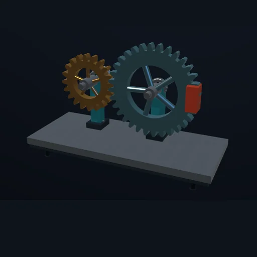
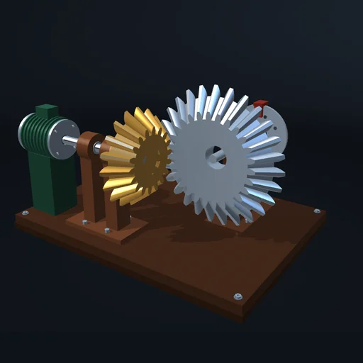
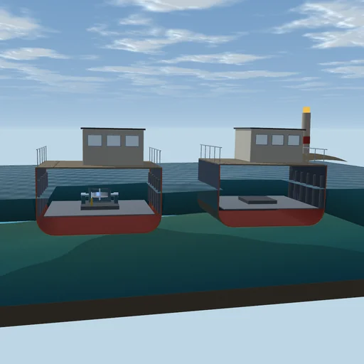
Two hulls roll in the same beam sea; one carries a spinning flywheel in a gimbal. Let it precess against the roll, set its brake and its speed, and compare the rolls; then send a heavy sea and drive the gimbal into its stops.
What happens
Two hulls of 300 t roll side by side in the same beam sea; the left one carries a gyro stabilizer in its engine room. Each hull rolls by I·d²φ/dt² = M_wave − c·dφ/dt − Δ·g·GM·sin φ − H·cos α·dα/dt, with a natural period of 6.88 s. The flywheel of 100 kg·m², spinning at up to 9000 rpm about the vertical, sits in a gimbal that tips fore and aft by the precession α: the roll makes it precess, and the precession's gyroscopic moment opposes the roll. The two gyroscopic moments do no work, so the stabilizer takes energy out of the roll only through the gimbal's brake - a damper of limited torque - and its stops. A motor keeps the spin.
In a sea of 50 kN·m at the hull's own period the bare hull rolls by 12.2° and the stabilized one by 1.9°, while its gimbal precesses by 28.8°. At 4500 rpm the roll is 5.4°. A soft brake of 1500 N·m·s leaves 0.6° of roll but swings the gimbal by 32.9°; a hard one of 20000 N·m·s holds the gimbal to 21.1° and lets the roll grow to 4.6°. In a sea of 150 kN·m the gimbal strikes its stops at 70°: the roll is 14.0°, against the bare hull's 34.2°. From rest the motor takes 55 min to bring the flywheel to 99 % of its speed.
Model: a rigid hull with a linear righting arm of GM = 0.8 m and 5 % damping, in a regular or an irregular sea; the gimbal's stops a stiff spring with a damper; no coupling with pitch, heave or yaw. RK4 with steps of 1/120 s; the journal closes on the sea's and the motor's work.
Try this
Compare the two rolls, then switch the stabilizer off and on. Change the brake and the flywheel’s speed and watch the precession; send a heavy sea and see the gimbal strike its stops.
Equations used in the module
Equations
I·d²φ/dt² = M_wave − c·dφ/dt − Δ·g·GM·sin φ − H·cos α·dα/dt
I_g·d²α/dt² = H·cos α·dφ/dt − k_g·sin α + M_brake + M_stop
H = J·Ω
I·dφ/dt + H·sin α = const without the sea