Engineering
Marine chronometer and navigation
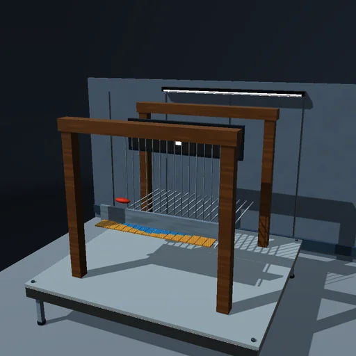
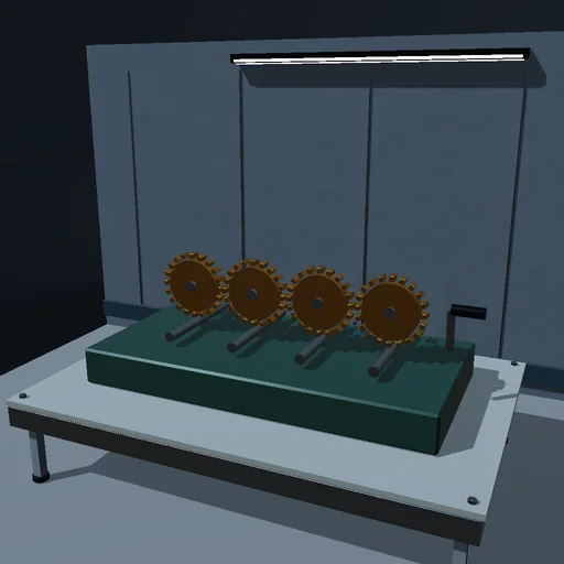
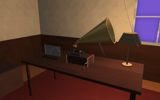
Keep time at sea by lamplight: a balance wheel on its hairspring, kicked once a beat by a detent escapement, beats seconds in a gimballed box. Warm the cabin and watch an uncompensated balance lose two minutes a day, then let the bimetal rim take the linear error out and leave the small middle-temperature error; lock the gimbals in a heeled box and an out-of-poise balance gains or loses with its amplitude, almost not at all near 220 degrees; set the voyage length and read how far east or west a navigator would place the ship. The impulses given are booked against every loss.

What happens
A balance wheel of 8 g and 22 mm radius on its hairspring beats once a second; a detent escapement gives it a fixed impulse of 36 µJ exactly at the upward zero crossing, located inside the step by a cubic Hermite refined by Newton, against air drag and pivot friction. Temperature softens the hairspring and swells the rim; the bimetal rim’s compensation removes the linear part and leaves the middle-temperature error. With the gimbals locked in a heeled box an out-of-poise balance feels a gravity torque. RK4 at 1 ms; the rate in seconds a day comes from the crossings, the closed form from the exact Duffing period, the poise term 2 J1(A)/A and the viscous shift.
Try this
Read the baseline rate, then warm the cabin with and without compensation; lock the gimbals, heel the box and put the balance out of poise at different amplitudes; set the voyage and read the error of longitude.
The model and its limits
A rigid balance on a linear hairspring with a cubic isochronism term, an instantaneous detent impulse, lumped drag and friction, a quadratic temperature law. Rates are those of this idealized movement, not of any maker’s chronometer.
Equations used in the module
Equations
I(T)·α = −k(T)·θ·(1 + ε·θ²) − c·ω − τ_f·tanh(ω/ω_f) − m·g·e·sin φ·sin θ
k(T) = k0·(1 + α_s·ΔT),  I(T) = I0·(1 + (α_r − κ·(α_r − α_s))·ΔT + κ·β·ΔT²)
ω+ = √(ω² + 2E_i/I) at θ = 0,  E_i = π·c·ω·A² + 4τ_f·A
rate = 86400·(T_ref/T − 1),  Δλ = rate·days/240