Engineering
Subsea cable laying
Pay a subsea cable out over the stern of a cable ship and match the payout to the ship's speed, watching the tension, the angle of descent and where the cable touches the seabed. Speed the ship up or stop it, hold the cable back by tension instead of speed, change to a heavy power cable, and open a trench across the route to see the cable span it or lie on its floor.
What happens
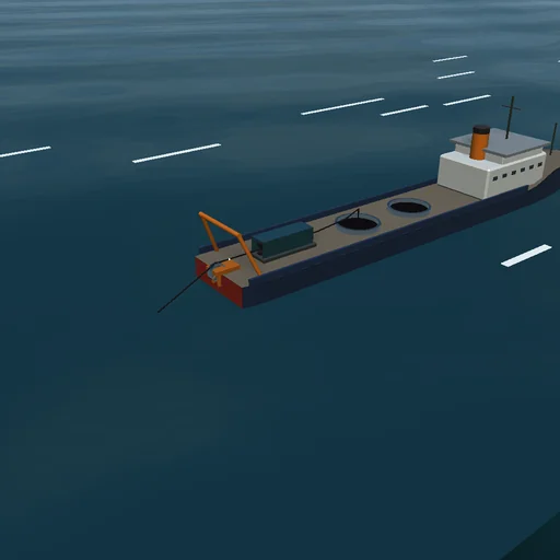
A cable ship steams along its route and pays a subsea cable out over its stern sheave, 6 m above the water, through a linear cable engine; the cable hangs through 300–1000 m of sea and lies down on the seabed behind the ship. The model is a chain of lumped masses, one for every sixteenth of the depth: elastic segments that only pull, the cable's weight in water, the water's added mass and drag across and along the cable, relative to a current. The seabed holds the landed cable by friction. The light telecom cable is 17 mm thick and weighs 0.46 kg/m in air, 2.23 N/m in water; the heavy power cable 120 mm, 36 kg/m and 239.4 N/m. The engine holds the payout speed, slipping above its limit, or a hold-back tension. The diorama is at one hundredth of the size: the ship, 130 m long, is 1.3 m.
At 1 m/s with 4 % slack the light cable comes down in a straight line at 26.0°, where its weight across it equals the drag; it leaves the sheave at 28.6° with 1137 N and touches down 1038 m astern without tension, and the slack lands on the bed. The heavy cable hardly feels the drag: it falls at 73.8° and touches down 150 m astern, with 121.4 kN at the sheave. Held back at 1.5 times its weight in water over the depth, the light cable is laid taut with 533 N at the bottom, the touchdown 1121 m astern, the sag bend's radius 239 m; the heavy one keeps 57.9 kN at the bottom. Speed the ship up to 1.2 m/s without more payout and the tension climbs until the engine slips at 10 kN, lifting the cable off the bed with 8.86 kN at the bottom. Stop the ship with the engine running and the heavy cable hangs straight down with 121.0 kN while the payout piles on the bed. A trench 100 m deep and 700 m wide asks for 34 m more cable: with 4 % slack the cable lies on its floor, with none it spans the trench under tension. A current of 0.3 m/s with the ship steepens the departure to 38.2°.
Model: in the plane of the route; no bending stiffness, so cable landing slack folds onto the bed; no torsion and no ship motion in waves; the laid cable behind the chain is fixed. RK4 with steps up to 1.35·l/c, l being a segment and c = sqrt(EA/m) the speed of tension waves, which the engine's drive absorbs. The energy journal of the ship's work, the paid-out cable, the engine's brake, the water and the seabed closes, and the cable paid out equals the free cable plus the laid.
Try this
Watch the cable come down to the seabed at the set speeds, then speed the ship up without more payout and see the tension at the bottom rise. Stop the ship, switch to tension control and to the heavy cable, and open a trench ahead of the touchdown point.
Equations used in the module
Equations
w·cos φ = ½·ρ·C_n·d·V²·sin²φ
T = EA·max(ε, 0),  m·λ·dv/dt = ΣT + w·λ + F_drag + F_bed
T_top − T_b = w·d + m·g·h;  R_bend = T_b/w
U ≥ V:  S = U/V − 1,   T_b > 0:  U = V/(1 + T_b/EA)