Engineering
Vehicle suspension
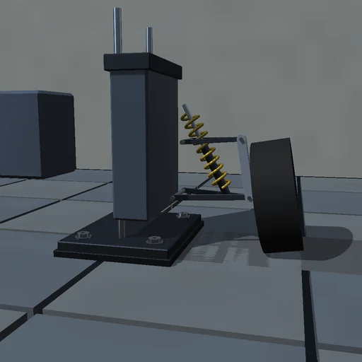
Run a quarter car over a 50 mm bump at 10 m/s: the wheel follows the road on its tyre spring, the body answers through the coil-over at its ride frequency near 1.4 Hz while the wheel hops at twelve, both read against the linearized closed forms. Soften the damper and the body floats and keeps oscillating; stiffen it and the bump hits harder but settles at once. Move the upper mount inboard and watch the camber gain in bump change. The road’s work on the tyre is booked against the stored energy, the damper’s and the tyre’s heat.
What happens
A double-wishbone quarter car on a test rig: the lower arm’s angle and the body’s height are the two coordinates, 40 kg of wheel and upright ride on the lower arm’s outer joint, the upper joint follows from the two circles of arm and upright so the camber changes with travel, and a coil-over between the arm and the body gives spring and damper forces through its length rate. The tyre is a spring with damping that fades in over its first two millimetres so lift-off stays continuous; a sin² bump runs under the wheel at the car’s speed. The Lagrangian mass matrix couples body and arm; RK4 at 50 µs books the road’s work against the stored energy and the damper and tyre heat.
Try this
Watch the wheel take the bump and the body answer a beat later; read the ride and wheel-hop frequencies against the linearized values; soften and stiffen the damper; move the upper mount and compare the camber gain.
The model and its limits
A planar quarter car with a point-contact tyre, no anti-roll bar, bushings or tyre enveloping, linear spring and damper, a smooth bump. Frequencies and forces are those of this idealized rig.
Equations used in the module
Equations
(M+m)·z″ + m·L·cos q·q″ − m·L·sin q·q′² = F_t − (M+m)·g
m·L·cos q·z″ + m·L²·q″ = F_t·L·cos q − m·g·L·cos q − F_s·dL_s/dq,  F_s = k·(L_s − L_0) + c·(dL_s/dq)·q′
z_road = h·sin²(π·(v·t − s_0)/λ)
W_road = ΔE + Q_damper + Q_tyre