Engineering
Aerial rescue ladder
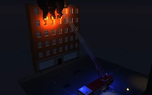
At night before a burning house a fire truck stands on its four outriggers and raises its turntable ladder to a window on the top floor. The four telescopic sections bend as a stepped cantilever whose closed-form deflection agrees with the unit-load integral, and the ladder is drawn bent by it, magnified. When a second person steps into the cage the tip drops by m g cos θ/k and overshoots, then sways at the first bending frequency sqrt(k/m_eff)/2π, dying away with the logarithmic decrement 2πζ; a gust sets it swaying too. Draw the outriggers in and the pads share the load ever more unevenly - at 1.5 m one lifts while the cage sways, at 1.2 m the truck would tip. The load chart gives the safe load against the reach, and the work of the loads is followed into the sway and the damping.
What happens
A turntable ladder of four telescopic sections, each 6.8 m long, on a truck of 12 t with a 3.2 t turntable. The sections extend together, each protruding 0.6 to 5.8 m beyond the one below, so the ladder is 8.6 to 24.2 m long; their bending stiffnesses are 1.0·10^8, 5.5·10^7, 3.0·10^7 and 1.5·10^7 N·m² and their masses 1100, 800, 560 and 380 kg. Where sections overlap their stiffnesses and weights add: a stepped cantilever, clamped at the turntable. Its weight and the 180 kg cage with its load, resolved across the axis (cos θ), bend it; the deflection is integrated in closed form on every segment (the moment is a quadratic there) and agrees with the unit-load integral of M m/EI to 10^-12. The first bending mode is a Rayleigh oscillator of the tip: k from the deflection under a unit tip force, m_eff = cage + the weight per metre times the square of that shape, damping ratio 3 %. A person of 90 kg stepping in is a step load with a mass jump (momentum kept); a gust of 18 m/s pushes with a drag rising as sin² over 2 s. Implicit midpoint steps of 1 ms keep the ledger exact. The truck is a rigid chassis on four equal pad springs at 1.6 and −3.9 m along it and ±1.2 to ±2.4 m across: a pad that would pull lifts and three carry the load; with the resultant outside the pads the truck would tip. The loads at which a pad lifts, at which the truck tips, and the safe load (stabilising moment 1.5 times the overturning one, at most 270 kg) follow in closed form from the moments about the pads’ edges.
Try this
Watch the tip drop and sway when the second person steps in, and read the sway frequency against the closed form; add a gust; draw the outriggers in to 1.5 m and watch a pad lift during the sway, to 1.2 m and the truck would tip; extend the ladder fully and lower it to see the safe load fall with the reach.
The model and its limits
A linear beam in its plane only, without axial shortening, twist or sideways sway; one bending mode; a rigid chassis on equal pad springs; the cage at the tip, statics on the undeflected geometry. Loads and limits are those of this idealized truck, not an operating table.
Equations used in the module
Equations
EI(s)·d²w/ds² = M(s) = F·(L − s) + Σ q_j·∫(t − s) dt,  δ = ∫ M·(L − s)/EI ds
k = 1/w_1(L),  m_eff = m_c + ∫ μ·(w_1/w_1(L))² ds,  f = √(k/m_eff)/2π
m_eff·a + c·v + k·y = k·δ_s(t),  c = 2ζ·√(k·m_eff),  Λ = 2πζ/√(1 − ζ²)
R_i = W/4 + B·(x_i − x_c) + C·z_i,  P_tip = Σ m_j·a_j/(−a_c),  P_safe = (M_s/1.5 − M_o)/(−a_c)