Engineering
Deployable bridge
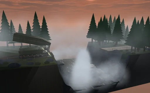
At first light an olive-green launcher stands at the edge of a foggy river gorge with an 18 m steel scissor bridge folded on its hull. One hydraulic drive lifts it on the launch arm, raises it through the vertical and opens the scissor until the far end glides level over the water, x = −2a cos φ, and lands on the far bank; the hydraulic work is followed into the bridge’s height, its motion and the friction to the joule. Raise the stabiliser blade and the outstretched 9 t bridge outweighs the launcher about its front tracks: it would tip at 152.7°, where the closed form puts it; above 11.8 t the relief valve cannot lift the bridge at all. Then a 24 t truck comes out of the fog and crosses: the span sags a further 45 mm, drawn magnified, its stress and safety against yield follow the influence lines, and without damping the ringing it leaves behind follows the closed form - at 36 km/h the two axles all but cancel.
What happens
An 18 m scissor bridge of two rigid 9 m halves, 4.5 t each, hinged at the deck line; the near end rides on a 1.6 m launch arm on the launcher’s nose. One drive turns the launch angle φ of the first half from 0 (folded back over the hull) to π: the arm swings by a smootherstep that is done at φ = π/2 + 0.25, the scissor opens by a quadratic blend around the vertical and then as ψ = 2φ − π, where the far end glides level at deck height, x = −2a cos φ, and J = m a² (5/3 − cos 2φ). The generalised inertia J(φ) and the potential V(φ) are exact. The hydraulic drive is flow-controlled (feed-forward of gravity and of dJ/dφ, a speed loop of 2·10^6 N·m·s, relief at 520 kN·m), friction 10^5 N·m·s plus 20 kN·m (smoothed); the arm runs at 2.9°/s. A discrete-gradient step of 2 ms makes the hydraulic work equal the potential gain, the kinetic energy, the friction heat and the seat loss to 10^-9 J. The 36 t launcher has its centre of mass 2.4 m behind the front road wheel, which stands 1.6 m behind the bridge’s end; the blade moves the support 1.3 m forward. It tips when the bridge’s moment about the support, static plus the rate of its angular momentum, exceeds 36 t·g·d_v; in the level glide cos φ_c = (e − M_v d_v/M)/a and the heaviest bridge is M_v d_v/(a + e). The seated span: EI = 6·10^8 N·m², 500 kg/m, section modulus 6·10^-3 m³, yield 355 MPa, three modes with 2 % damping, each integrated exactly between the axle entries and exits; deflection and moment by the mode-acceleration method. The truck: 24 t, 32 % on the front axle, wheelbase 4.2 m, constant speed, then 6 m/s² once clear. f1 = 5.31 Hz, v_cr = ω1 L/π = 688 km/h.
Try this
Watch the launch: the drive lifts the folded bridge, the scissor opens past the vertical and the far end glides level onto the far bank, the ledger closing to the joule; raise the blade and the launcher would tip at the closed-form angle; make the bridge 12 t and the relief valve cannot lift it. Start with the bridge in place and drive the truck across at different speeds and loads; set the damping to zero and compare the ringing it leaves behind with the closed form.
The model and its limits
First stage: the bridge halves are rigid while launching, the arm is massless and the linkage ideal; the launcher is a rigid body whose tipping is detected and stops the launch, not simulated; the lock is taken as closed once the far end lands. The span is a linear beam with three modes under two moving axle forces - the truck’s own mass and springs and the road’s roughness do not take part; no fatigue, buckling or local plate stresses. Numbers are those of this idealized bridge, not a classification table.
Equations used in the module
Equations
ψ = 2φ − π,  x_T = −2a·cos φ,  J = m·a²·(5/3 − cos 2φ),  V = m·g·a·sin φ
J_m·(ω₁ − ω₀)/h = τ_h − τ_f − ΔV/Δφ − (ΔJ/Δφ)·(ω₀² + ω₁²)/4  ⇒  W_h = ΔV + ΔK + Q_f
M_v·g·d_v = M·g·(e − a·cos φ_c) + dH/dt,  cos φ_c = (e − M_v·d_v/M)/a,  M_max = M_v·d_v/(a + e)
δ = P·b·x·(L² − b² − x²)/(6EI·L),  ω_n = (nπ/L)²·√(EI/μ),  v_cr = ω₁L/π,  A = 4Ω·|cos(ω₁L/2v)|·|P_f + P_r·e^(−iω₁d/v)|/(μL·ω₁·|ω₁² − Ω²|)