MakarovSuites
English
EnglishDeutschРусскийУкраїнськаFrançaisEspañolItalianoPolski
Contact & licences

Engineering

Lifeboat launching

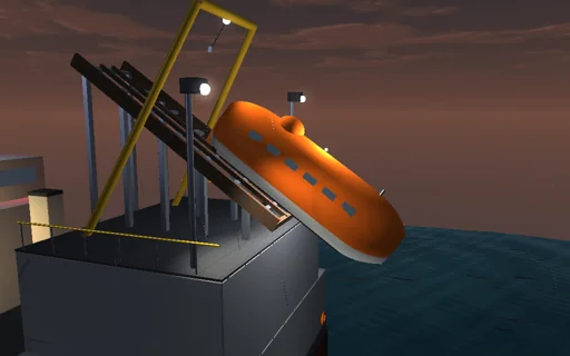
Release an enclosed free-fall lifeboat from the stern ramp of a supply vessel at dusk. It slides down the skids with Coulomb friction and leaves them at exactly sqrt(2 g L (sin theta - mu cos theta)), tips nose-down over the lip until the contact lets go, falls along a parabola and meets the dark sea where the closed form says, at the speed energy gives. It dives two metres deep, the buoyancy of its hull - nearly five times its weight - turns it up, it surfaces and the propeller drives it away while the pitch and heave die out. Read the loads at the bow, midship and stern seats: a higher drop enters faster and loads harder, a steeper ramp enters better aligned, trim by the stern lowers the lip. Every joule is followed into friction, drag, slamming and the water.
Lifeboat launching — Actual application image
Actual application image

What happens

An 8.5 m enclosed lifeboat of 8475 kg (30 persons), its centre of gravity 1 m above the keel and 0.6 m aft of the middle, radius of gyration 2.3 m, rests on a 35° stern ramp whose lip is 12 m above the sea. It slides 3.5 m with skid friction 0.1 at g (sin theta - mu cos theta), stepped exactly, and leaves at 5.81 m/s; it then tips over the lip on one sliding contact whose normal force comes from the constraint, and is released when that force vanishes, 1.72 s after the start. The flight is the exact parabola; the first hull section touches the water at 2.35 s, at 14.05 m/s on a 65.8° path with the bow 54° down. In the water the hull is 24 strips with lens-shaped sections of 39 m³ in all, 4.7 times its weight in buoyancy: buoyancy of every submerged section, added mass rho A normal to the keel with the von Karman slam force -max(dm/dt, 0) w, quadratic normal and axial drag, and 3 kN of propeller thrust once the stern is wet. RK4 steps of 1 ms; the energy ledger closes to the integrator’s order. Occupant loads are acceleration minus gravity at three seats, along the boat and through the spine; the combined index weighs them against 15 g and 7 g.

Try this

Watch the slide, the tip over the lip, the fall and the dive in slow motion; compare the exit and entry speeds with their closed forms; raise the lip and read the seat loads; try a steeper ramp and the bow loads drop; trim the ship by the stern and the lip comes down.

The model and its limits

A planar rigid boat in calm water, strip theory with a lens section, a momentum slam model, quadratic drag, no air drag, waves or roll, unfiltered loads. Loads are those of this idealized boat, not a certification test.

Equations used in the module
Equations
a_ramp = g·(sin θ − μ·cos θ),  v_exit = √(2·g·L·(sin θ − μ·cos θ))
N = (g·cos α − 2·ω·u + ω²·k) / (1/M + ξ_c·(ξ_c − μ·k)/I),  I·dω/dt = N·(μ·k − ξ_c)
(M + Σm_i)·a_n − S1·β = F_n − Σm_i·ω·u,  m_i = C_a·ρ·A_i,  f_i = −max(dm_i/dt, 0)·w_i
M·g·y0 = M·g·y + E_k + E_w + U_h + W_fric + W_drag + W_slam − W_thrust,  CAI = √((a_x/15)² + (a_z/7)²)

Related experiments

Back to catalogue
Deployable bridge — Actual application image

Engineering

Deployable bridge

At first light an olive-green launcher stands at the edge of a foggy river gorge with an 18 m steel scissor bridge folded on its hull. One hydraulic drive lifts it on the launch arm, raises it through the vertical and opens the scissor until the far end glides level over the water, x = −2a cos φ, and lands on the far bank; the hydraulic work is followed into the bridge’s height, its motion and the friction to the joule. Raise the stabiliser blade and the outstretched 9 t bridge outweighs the launcher about its front tracks: it would tip at 152.7°, where the closed form puts it; above 11.8 t the relief valve cannot lift the bridge at all. Then a 24 t truck comes out of the fog and crosses: the span sags a further 45 mm, drawn magnified, its stress and safety against yield follow the influence lines, and without damping the ringing it leaves behind follows the closed form - at 36 km/h the two axles all but cancel.

Thermal soaring — Actual application image

Engineering

Thermal soaring

Soar a white 15 m sailplane over a broad alpine valley on a strong summer afternoon: circle in a thermal under its cumulus, climb toward cloud base, then glide to the next cloud and climb again. The speed polar a V³ + b/V gives the minimum-sink and best-glide speeds and a best glide of 40; in a Gaussian thermal the bank that climbs best is a closed form through Lambert’s W - too shallow and the circle lies outside the core, too steep and the circling sink eats the lift. Between thermals MacCready’s speed to fly is the tangent from the expected climb to the polar, and the measured cross-country speed follows V c/(c + w_s). Switch the centring off and an off-centre circle sinks out of the lift; weaken the thermal and the sailplane lands in a field. Every joule of height and speed is followed from the rising air into the drag.

Seaplane takeoff — Actual application image

Engineering

Seaplane takeoff

Open the throttle of a 1450 kg floatplane on a glassy lake at dawn and watch it climb out of the water. At first the two floats carry the whole weight by Archimedes’ law and plough bows up; as the speed grows the planing bottoms ahead of the steps lift them by Savitsky’s law, the water’s drag rises to its hump - about 2.8 kN at 11 m/s, a fifth of the weight - and falls as the wing, whose lift grows with the square of the speed, unloads the floats. The pilot holds the planing trim with the elevator in the propeller’s slipstream and rotates near the closed-form unstick speed: the floats leave the water after about 420 m and the aircraft clears 15 m after about 740 m. Try a flat or a steep trim - one wets the floats and runs twice as far, the other stays stuck behind the hump - add weight, raise the flaps, take off into the wind or in chop, or abort the run.