Engineering
Clockwork drawing automaton
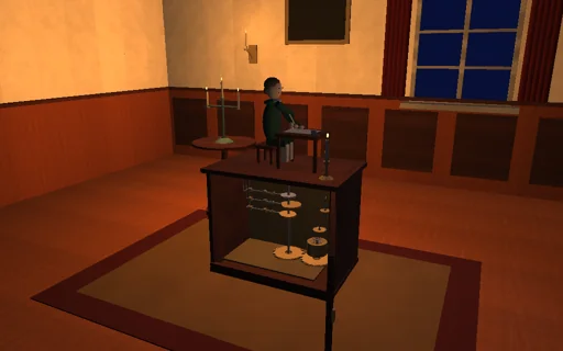
By candlelight in an eighteenth-century salon a clockwork boy draws with a quill. A mainspring, its torque falling as it unwinds, turns the program shaft, and a two-vane fly governs the speed by its air drag, so a drawing takes the closed-form time. Three cams cut from the drawing - Fourier series of the arm’s inverse kinematics - move the shoulder, the elbow and the pen lift through their followers and levers, and the ink line is the image of the cam profiles. Choose a circle, a figure of eight, a flower, a star or a ship; give the cams fewer harmonics and the corners round off; fold the fly’s vanes until the followers fly off their cams above the closed-form lift-off speed and the star is distorted; set the pen-lift cam late or lift too little and the connecting lines appear. Every joule of the spring is followed into the fly, the bearing, the contacts and the stop.
What happens
A mainspring of 0.0066 N·m/rad wound up to six turns (0.249 N·m, 4.69 J) turns the program shaft once per drawing. A train of 400 drives a fly of two 10 cm² vanes at 3 cm: their air drag, ρ Cd A (r ω)²/2 each with Cd 1.2, is a drag C ω² on the shaft with C = 2.49 N·m·s² at full vanes; with the bearing’s 0.01 N·m·s the steady speed is ω_ss = (−c_b + sqrt(c_b² + 4 C τ))/2C, 0.314 rad/s, and one drawing takes the closed-form (1/k_s)[s + c_b ln(s − c_b)] between the starting and the final torque, s = sqrt(c_b² + 4 C τ), plus the fly’s spin-up J ln 2/(C ω_ss) with J = 0.1 kg·m². The drawing - strokes joined by travels on which the arm holds still while the pen lifts and lowers - is sampled at 720 points; the inverse kinematics of an arm of 120 and 110 mm turns each into shoulder and elbow angles, levers of 40 mm turn those into follower lifts, and the first H harmonics (8 to 96) of the lifts and of a 5 mm pen-lift schedule are the three cams. Knife-edge followers of 0.12 kg on springs of 40 N/m with 10 mm preload touch their cams through a one-sided contact of 10^5 N/m with Hunt-Crossley damping: where k (y + y0) cannot supply m |y″| ω² a follower flies, and the lowest such ω along the cam is the closed-form lift-off speed. The followers set the arm, its forward kinematics places the quill, and the quill inks while the pen-lift lever holds it 0.6 mm into the paper (0.24 N). Shaft and followers advance together by the implicit midpoint rule in 1 ms steps with a discrete gradient of every spring and contact, so the spring’s energy goes into the fly, the bearing, the contact damping, the stop and the energy stored to round-off; a stop lever catches the shaft at the end of each revolution, located inside the step.
Try this
Watch the boy draw the circle in the closed-form time and draw it again on the weaker spring; choose the star and compare 16 and 96 harmonics; soften the follower springs to 10 N/m and fold the vanes below 1 % until the followers fly off their cams and the star is distorted; on the flower set the pen-lift cam 12° late, or the pen lift below 0.6 mm, and the connecting line appears.
The model and its limits
A teaching automaton, not a reconstruction of a particular historical machine: knife-edge followers with constant reflected masses, a rigid arm moving in the plane of the paper, a linear mainspring without stop-work or fusee, the fly’s inertia fixed while its vanes change, the quill’s pressure and the paper’s friction read off the linkage and not fed back into the drive; no flexible wrist, no ink spreading in the paper.
Equations used in the module
Equations
τ = k_s·(W − φ),  C·ω_ss² + c_b·ω_ss = τ,  C = ρ·C_d·A·r³·G³
T = (1/k_s)·[s + c_b·ln(s − c_b)] from τ_end to τ_0,  s = √(c_b² + 4C·τ),  + J·ln 2/(C·ω_ss)
y_i(φ) = a_0 + Σ (a_k·cos kφ + b_k·sin kφ),  k ≤ H,  θ = θ_0 + y/l_lever,  P = S + l_1·e(θ_1) + l_2·e(θ_1 + θ_2)
N = k_f·(y + y_0) + m·(y″·ω² + y′·α) ≥ 0,  ω_c² = min k_f·(y + y_0)/(m·|y″|),  W_spring = W_fly + W_bearing + W_contact + W_stop + ΔE