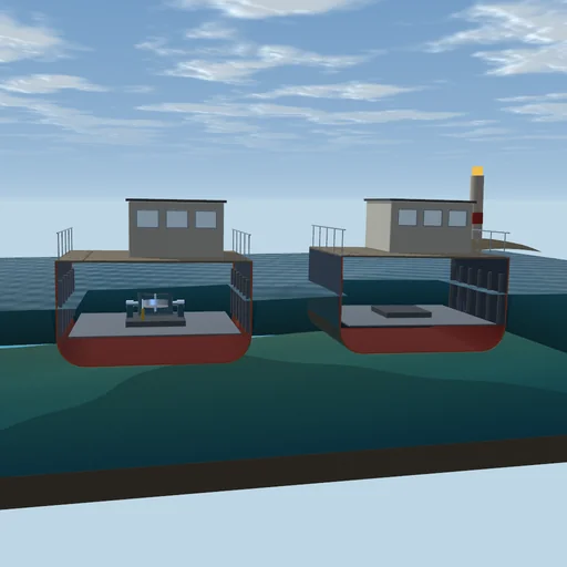
Engineering
Pneumatic tube mail
Send a capsule through the pneumatic tube of an office building: the blower's air pushes it along the floor, up the riser and through the diverter to station B or C. Change the capsule's mass and the blower's pressure, drill a hole in the riser, and switch off the air cushion to hear it strike the end.
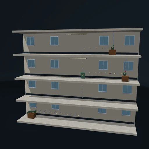
What happens
A tube of 100 mm runs 8 m along the ground floor from station A, rises to a diverter, and either turns along the second floor to station B, 22.28 m of tube from A, or climbs on to station C on the third floor, 24.28 m. A blower with a straight characteristic - at most 0.08 m³/s, and a shut-off pressure that you set - pushes air into the tube behind a capsule 0.25 m long; the air ahead leaves through the receiving station's vent of 40 cm². The air behind and the air ahead are two isothermal volumes that change with the capsule's position, and a little air leaks past the capsule. The capsule moves by the pressure difference on its face, against gravity on the slope, wall friction with μ = 0.2 (pressed harder in the bends) and drag. At 2.5 m before the end the station can close its vent to a bleed of 0.6 cm², and the capsule brakes on the air it compresses.
A capsule of 1 kg on a blower of 6 kPa reaches B in 3.20 s and, with the vent left open, strikes the end at 8.0 m/s; with the cushion it arrives at 0.39 m/s after 8.72 s, creeping on the bleed. To C it takes 9.07 s. A capsule of 3 kg needs m·g/A = 3.75 kPa to climb the riser: on 6 kPa it arrives in 10.9 s, a hole of 3 cm² in the riser makes it 12.8 s, and on 3.5 kPa it stops at the riser's foot, 8.65 m out.
Model: isothermal ideal gas in two volumes, orifice flows linear below 50 Pa; the capsule one degree of freedom along the route; no pressure waves, no heating of the air. Steps of 0.2 ms; air is neither made nor lost.
Try this
Send the capsule and follow it up the riser; then switch off the air cushion and see it strike the end. Make it heavier or the blower weaker until it stalls at the riser’s foot, or drill a hole in the riser.
Equations used in the module
Equations
p = m·R·T/V
dm_b/dt = Q_fan − Q_past − Q_hole,  dm_a/dt = Q_past − Q_vent
M·d²s/dt² = (p_b − p_a)·A − M·g·sin τ − μ·N − c·v
Q_fan = ρ₀·Q_max·(1 − Δp/Δp₀)