Engineering
Centrifugal separator
Spin two tubes of large and small beads and stop the run when the large ones are down while most of the small ones stay in suspension; compare short and long runs, speeds and a thicker liquid. Then fill a balance tube short and watch the rotor whirl through its critical speed: on a slow ramp the imbalance switch trips, on a fast one the rotor gets through, and with the brake off it shakes again as it coasts down.
What happens
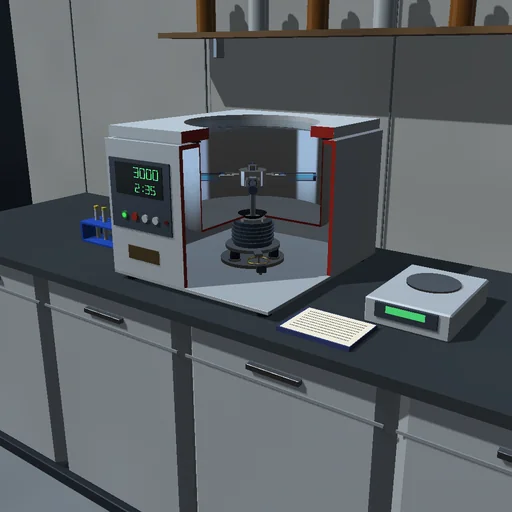
A benchtop centrifuge with a four-place swing-out rotor spins two tubes of 10 mL of water with two sorts of polystyrene beads, 3 µm and 1 µm across, each 1 % of the volume; the other two buckets carry balance tubes of water. The buckets hang on pivots 90 mm from the axis and swing out until gravity and the centrifugal acceleration together point along them; swung out, the liquid lies between 118 and 183 mm from the axis. A bead drifts outwards at its Stokes velocity K·ω²·r with K = d²·(ρ_p − ρ_l)/(18μ), so beads three times larger move nine times faster, and the separation is set by ∫ω²dt: the column clears from the meniscus, the rest of the suspension thins, and r_b·(1 − e^(−K·∫ω²dt))/(r_b − r_m) of a sort reaches the bottom. Motor and rotor, 4.36 kg, stand on rubber mounts of 7600 N/m: a balance tube filled short puts their mass centre off the axis, and they whirl as a Jeffcott rotor with a critical speed of 399 rpm. The drive follows its ramp within 2 N·m and 500 W.
At 3000 rpm the bottom of a tube feels 1841 g. The default run - up at 500 rpm/s, 3 min at speed, braked - collects ∫ω²dt = 18.2·10⁶ rad²/s: all the large beads are down, as they need 17.6·10⁶, but only 13.8 % of the small ones. One minute takes 41 % of the large beads; ten minutes take 43 % of the small ones, and 5000 rpm takes 37 % in 3 min. A liquid ten times more viscous lets only 12.5 % of the large beads down. With a balance tube 2 g short the whirl peaks at 0.39 mm at the critical speed and settles to 70 µm, away from the heavy tube: above the critical speed the rotor turns about its mass centre. With 10 g short the whirl reaches the 1.8 mm switch after 0.99 s and the run is braked; at 1000 rpm/s the rotor gets through at 1.65 mm. Coasting down with the brake off, it crawls through the critical speed and the 2 g whirl grows to 0.56 mm. Windage takes 9.9 kJ of the motor's 12.0 kJ.
Model: the buckets swing quasi-statically and the liquid turns with the rotor; a dilute suspension without hindered settling; Stokes drag (Reynolds number 0.14 for a 10 µm bead at 5000 rpm); no Brownian diffusion; the mounts move horizontally. RK4 with steps of 1/1200 s; the journal closes on the motor's work against the brake, windage, bearings, the mounts' damping and the rotor's energy, and every bead is in suspension or at the bottom.
Try this
Watch the sample tubes clear from the top and stop the run when the large beads are down while the small ones still cloud the tube. Then fill a balance tube short and slow the ramp to see the whirl trip the imbalance switch.
Equations used in the module
Equations
v = K·ω²·r,  K = d²·(ρ_p − ρ_l)/(18μ)
n_b/n = r_b·(1 − e^(−K·∫ω²dt))/(r_b − r_m)
g·sin θ = ω²·(R + l·sin θ)·cos θ
M·d²z/dt² + c·dz/dt + k·z = M·e·(ω² − i·dω/dt)·e^(iφ)
J·dω/dt = T_motor − T_loss + e·Im[(k·z + c·dz/dt)·e^(−iφ)]