Engineering
Industrial CT scanner
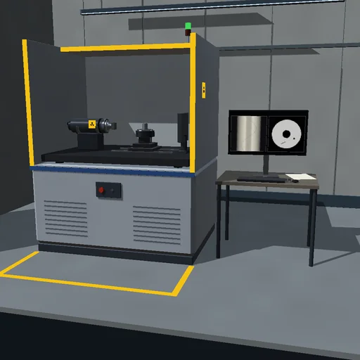
Scan a cast aluminium part view by view and watch its slice build up on the monitor from the X-ray projections, then find the hidden pore and measure it. Lower the dose, cut the number of views, turn on the full spectrum and move the turntable's axis off the beam to see noise, streaks, cupping and doubled edges, and tell the reconstruction the axis offset to rebuild a sharp image.
What happens
An industrial CT cabinet scans one slice of a cast aluminium part. A micro-focus tube limited to 50 W radiates Kramers' bremsstrahlung through a 2 mm aluminium filter; at 150 kV the detector's signal-weighted energy is 69 keV, where aluminium attenuates 64 and steel 673 per metre. A slit shapes the beam into a fan; the part turns on a table 0.375 m from the focal spot, and a flat panel 0.75 m away reads a row of 192 pixels of 0.8 mm. The casting, 52 mm across, hides a gas pore and a crack beside its bore, in one variant round a steel pin; it is made of discs and an ellipse, so each ray crosses it along exact chords. Each view's counts carry their Poisson noise, the line integrals ln(I₀/I) form the sinogram, and every view is filtered and back-projected at once onto 128 × 128 pixels of 0.5 mm.
Without noise, 360 views reconstruct the calibration cylinder to its μ within 0.01 % and the casting with an RMS error of 1.02 per metre, all at the edges; the 3 mm pore measures 2.97 mm at half depth. At 40 µA and 50 ms a view sends 34 516 noise-equivalent photons into the central pixel: the noise in the wall is 1.73 per metre, the pore's CNR is 31, the scan takes 33.8 s. Four times the current halves the noise, a quarter of the views doubles it, the Shepp-Logan kernel lowers it by a fifth. At 1/200 of the dose the CNR falls to 2.6: the 3 mm pore still shows, a 1 mm pore sinks below the Rose criterion. 30 views leave streaks: error 7.2 per metre. With the axis 1 mm off the central ray every edge splits into two half steps 2 mm apart, error 10.8; told the offset, the reconstruction rebuilds from the stored sinogram in 3 s, error 1.7. The full spectrum hardens through the cylinder, and its image cups by 12.6 %.
Model: Kramers' continuum in 16 energy bins without tungsten's lines; NIST coefficients interpolated log-log; no scatter reaches the detector; each pixel averages four rays, its flat field known exactly, a count of 0 read as 1. Fan-beam filtered back projection for a flat detector (Kak and Slaney), rebuilt at 120 views a second when the filter or the assumed axis changes. The table steps in the shortest time its 0.5 N·m allow and settles for 20 ms; events fall at the same times for any step, here 1/120 s. The energy journal closes from the tube's input to anode heat, shielding, filter, part and detector; the default scan leaves 2.47 mGy in the slice.
Try this
Watch the slice build up on the monitor, find the pore and read its diameter. Then lower the current and the exposure, cut the views, turn on the full spectrum, move the axis off the beam and correct it, and compare noise, streaks, cupping and doubled edges.
Equations used in the module
Equations
I = I₀·exp(−Σ Δμ·l),  p = ln(I₀/I),  P_x = k·Z·U²·I_tube
E_eff = Σ N·E²/Σ N·E,  N_eq = Σ N·E/E_eff,  ⟨N⟩ = σ_N² = N_eq·exp(−p)
f(x, y) = Δβ·Σ (D/L)²·Q(s′),  Q = (p·D/√(D² + s²)) * h/2
σ² = Σ (∂f/∂p)²/N ∝ 1/(N_v·I₀),  CNR = (f_ring − f_pore)/σ
t_step = 2·√(Δθ·J/τ),  D = E_absorbed/m_slice