Engineering
Turning lathe
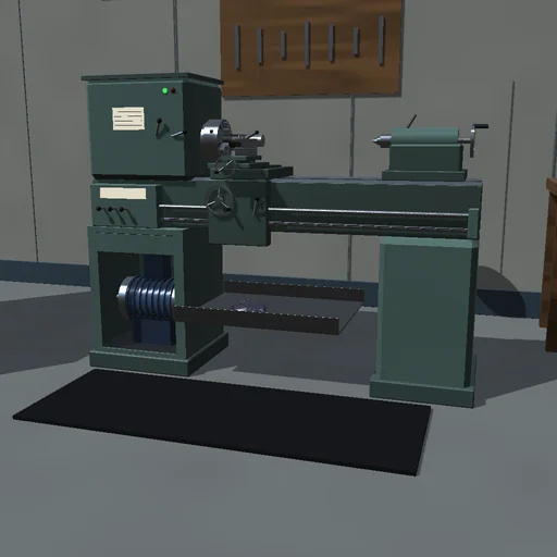
Turn a stepped shaft from a 60 mm steel bar on an engine lathe: the carriage feeds the tool along the turning bar pass after pass while the spindle slows under each cut. Change the feed, the depth and the nose radius to compare roughness, power and time, and take a deep pass at high speed to stall the motor.
What happens
An engine lathe turns a 60 mm steel bar held in a three-jaw chuck, 160 mm of it out of the jaws. A 5.5 kW induction motor of 1500 rpm drives the spindle through a gearbox set for the chosen speed. Its torque follows Kloss's curve up to a breakdown torque 2.5 times the rated one at 14.4 % slip, so the spindle slows a little under every cut and stops when a cut asks for more. The carriage is geared to the spindle and moves the tool by the feed every revolution. The cutting force follows Kienzle, F_c = k_c1.1·a_p·f^(1 − m_c), with 1700 N/mm² and 0.25 for steel, so the cutting power is the specific energy k_c times the rate the metal is removed. The program turns the bar pass after pass, each taking at most the set depth, into one step, two steps or a taper.
Set to 800 rpm, the spindle idles at 799.3 rpm. The first pass, 2 mm deep at a feed of 0.2 mm, meets 1017 N and 29.5 N·m and takes 2.44 kW: the spindle settles at 789.1 rpm and the pass lasts 38.8 s. The two steps, 48 mm over 100 mm and 36 mm over the last 50 mm, take six passes and remove 141.4 cm³; the cut's work is k_c·V = 359 kJ, 2.54 J for every cubic millimetre. Switched off, the spindle runs down in 9.2 s. A feed of 0.1 mm leaves cusps of 1.56 µm and needs 231 s for one step; a feed of 0.4 mm leaves 25.4 µm in 59 s, and its thicker chip takes 29 % less energy for the same metal. One 6 mm pass at 0.3 mm asks 111.6 N·m: at 1000 rpm the motor carries it at 921 rpm and 10.8 kW, but at 1250 rpm the gearbox gives at most 108.3 N·m and the spindle stalls 0.67 s after the tool meets the bar.
Model: spindle, chuck, gears, the bar (its inertia falling as it is turned) and the motor's rotor seen through the gearbox are one rotating body with bearing drag M₀ + c·ω; the motor is a static curve without electrical transients or heating and trips at once when locked. The feed force, two fifths of the cutting force, loads the feed train; the passive force does no work. The cutting force does not depend on the speed, the tool does not wear and nothing deflects; the roughness is the kinematic cusp of the nose and the trailing edge, and the chip is not modelled. RK4 with steps of at most 1 ms, cut where the tool enters a new cell of the profile; the journal closes on the mains' air-gap energy = rotor slip + friction + cutting + feed + the chips' and the spindle's kinetic energy, and no metal is made or lost.
Try this
Watch the bar being turned pass after pass and the spindle slowing under each cut. Then change the feed to compare roughness and time, and set a deep cut at a high speed to stall the motor.
Equations used in the module
Equations
T(s) = 2·T_k·s·s_k/(s² + s_k²),  s = 1 − i·ω/ω_sync
J·dω/dt = i·T(s) − M₀ − c·ω − F_c·(r + x)/2 − 0.4·F_c·f/2π
F_c = k_c1.1·a_p·f^(1 − m_c),  dz/dθ = −f/2π
V = π·∫(r² − x²)dz,  W_cut = k_c·V
R_t = r_ε − √(r_ε² − f²/4) ≈ f²/(8·r_ε)