Engineering
Walking excavator
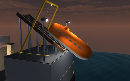
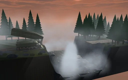
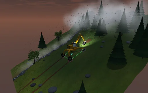
Work a yellow spider excavator on a steep alpine meadow in the drizzle. Its body is levelled on four telescopic legs, two clawed pads and two wheels, and the support polygon between them is drawn on the grass with the plumb line from the centre of mass: green while the margin is wide, red near tipping. The four pad loads are statically indeterminate and follow from the pads’ compliance; a pad that would pull lets go. Dig a trench, lift the full bucket and swing it: the hydraulic work goes into height, cutting and valve heat to the joule. On wet turf the machine slides at atan μ = 33° long before it tips. Face downhill on hard soil and the breakout force tips it over its front pads at the closed-form force, unless a lower relief pressure stalls the bucket first. Lift a leg: the uphill front leg comes free, a downhill one is refused until the boom swings over.
What happens
An 8.4 t spider excavator: chassis and legs 4.3 t, turret with cab and counterweight 2.9 t, a 3.4 m boom of 650 kg, a 2.3 m arm of 320 kg and a 0.95 m bucket of 220 kg that holds 540 kg of soil. Two clawed pads and two wheels stand 2 m ahead and behind and 1.9 and 1.6 m to the sides on a 28° slope; the legs level the body about its centre 1 m above the ground. The weight of every part and the soil’s force on the teeth give a resultant whose line meets the slope at the centre of pressure; its distance to the nearest edge of the polygon of the pads on the ground is the tipping margin. The chassis is rigid on four pad springs of 2 MN/m: three equations of statics and the compliance give the four loads, and a pad that would pull lets go. The machine slides when the in-plane force exceeds μ = 0.65 times the normal force. Levelled and facing uphill the plumb point lies at x_c/cos α − H tan α and the slope tips it at acos(−x_c/√(a² + H²)) − atan(H/a) = 64.9°; unlevelled at atan((x_c + a)/(H + y_c)) = 50.8°. The arm reaches out and the boom lowers the teeth 0.25 m into the slope; the bucket curls 1.9 rad at 0.6 rad/s against a cutting resistance of 12, 30 or 55 kN that grows as it fills and falls as the teeth leave the ground, acting on the machine against the teeth’s motion; its 100 mm cylinder on a 0.24 m lever holds at the relief pressure. The boom lifts dynamically under its 100 mm cylinder with a velocity loop and a load-holding valve, semi-implicit at 2 ms; slew, arm and bucket move quasi-statically. Tipping, sliding and the relief stall are located inside the step and stop the cycle. A step: the leg retracts until its pad lets go, swings 0.6 m and is preloaded again. Hydraulic work = potential + cutting work + kinetic + valve heat.
Try this
Watch the stance’s margin and the four pad loads, then the dig cycle with its hydraulic ledger; steepen the slope past atan μ, switch the levelling off, narrow the stance across the slope and swing the full bucket downhill; face downhill on hard soil with claws, then with a lower relief pressure; weaken a pad; step a leg, then a downhill leg, then the same with the boom swung over.
The model and its limits
First stage: a rigid machine on four linear pad springs; the legs’ masses are lumped into the chassis and a swinging leg changes nothing in the statics. Arm, bucket and slew move quasi-statically, only the boom lift is dynamic, and the stability is quasi-static, without the inertial forces of the moves. The soil is a cutting resistance with a fixed profile acting against the teeth’s motion, not a soil-mechanics model; the pads do not sink, plough or slide partly, and one friction coefficient serves the whole machine. Tipping and sliding are detected and stop the cycle; the fall or the slide itself is not simulated. The boom’s path is not checked against the ground. One relief pressure serves both cylinders and their levers are constant. Not a rating of any real machine.
Equations used in the module
Equations
p = r_c − (r_c·n / up·n)·up,  x_p = −M_z/F_n,  z_p = M_x/F_n,  margin = min over edges of the distance from p to the support polygon
N_i = k_i·(c0 + c1·x_i + c2·z_i − u_i) ≥ 0,  ΣN_i·(1, x_i, z_i) = (F_n, −M_z, M_x);  equal pads: N_i = F_n/4 + F_n·x_p·x_i/(4a²) + F_n·z_p·z_i/(2(w_f² + w_r²))
levelled: α_tip = acos(−x_c/√(a² + H²)) − atan(H/a);  unlevelled: tan α_tip = (x_c + a)/(H + y_c);  sliding: tan α = μ
F_relief = (p·A·r − τ_g)/L,  F_tip = (a·W_n + M_zW)/(a·f_n − m_f);  W_hyd = ΔE_p + W_cut + E_k + Q_valve;  lift-off u* = 4N/k